
Large-scale structure integral hositing device and method

A technology of overall lifting and large structure, applied in the direction of lifting device, hoisting device, etc., can solve the problems of high price of self-locking feed-through jack, random deviation of the structure, unacceptable to the owner, etc., and it is easy to guarantee the safety. , easy to promote, fast effect

Inactive Publication Date: 2006-02-22
SOUTH CHINA UNIV OF TECH
View PDF0 Cites 23 Cited by
  • Summary
  • Abstract
  • Description
  • Claims
  • Application Information

AI Technical Summary

Problems solved by technology

The disadvantage of this method is that: the jacking jack is placed under the structure, and the structure is prone to random deviation, so full-height guide rails must be provided to ensure the vertical upward jacking movement
The disadvantage of the overall lifting method is that the self-locking through-hole jack is expensive, and only a small number of professional lifting companies will equip it. Therefore, this sub-project is generally contracted by professional lifting companies, and the price is very high, which is difficult for the owner to accept. mass promotion

Method used


Image

  • Large-scale structure integral hositing device and method
  • Large-scale structure integral hositing device and method
  • Large-scale structure integral hositing device and method

Examples


Embodiment 1

[0033] The lifting object is a large roof structure with a weight of 100t.

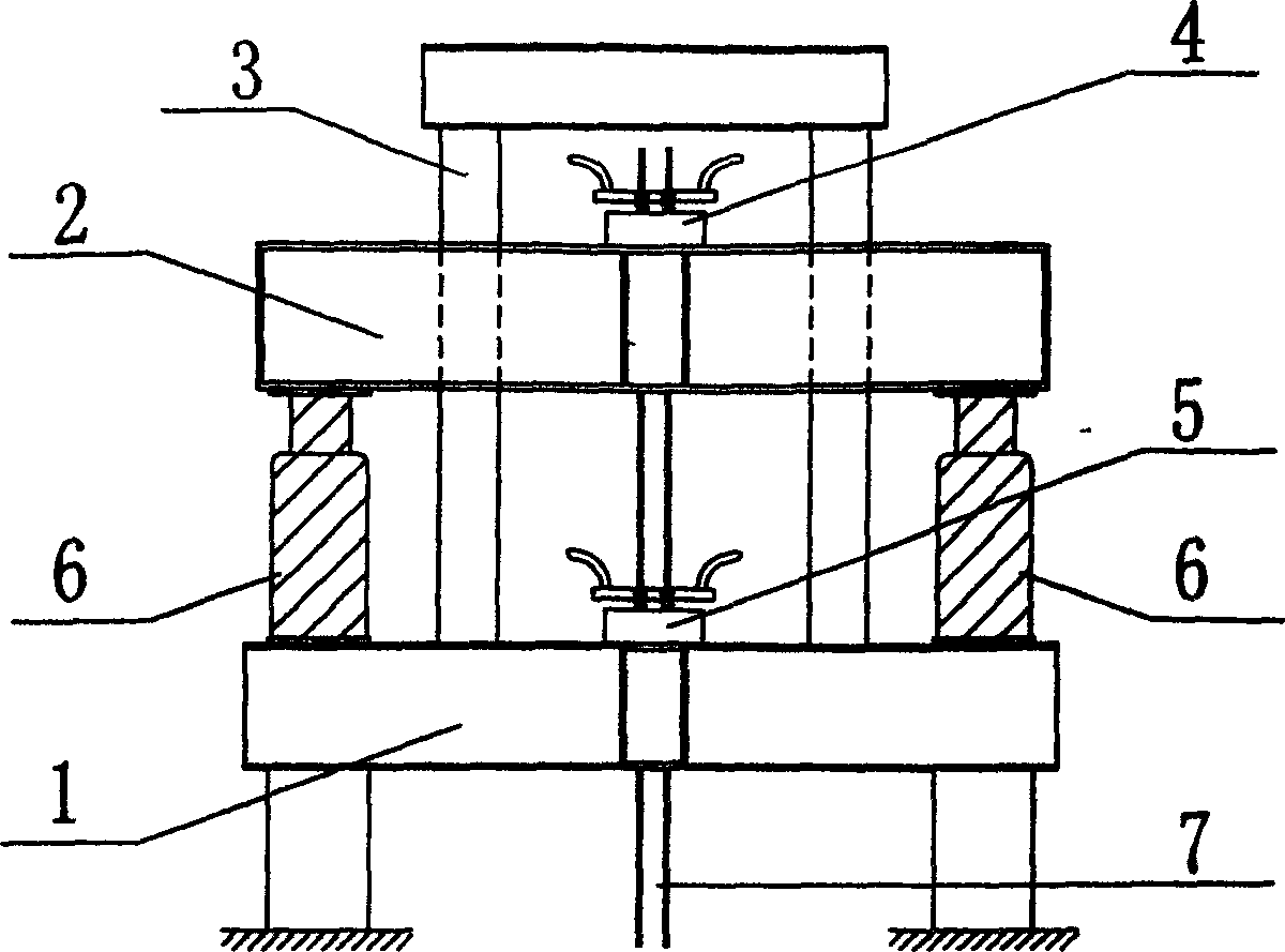
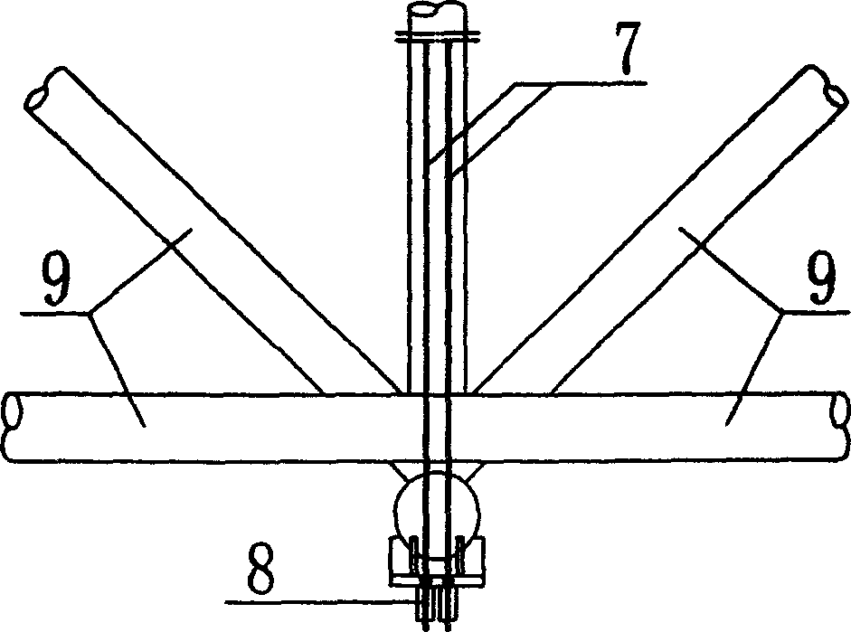
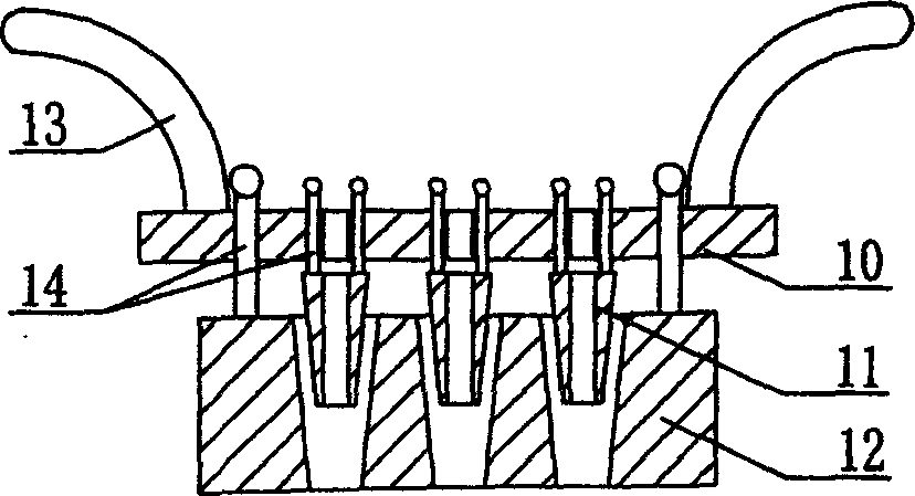
[0034] Such as figure 1 , 2 As shown, the lifting device used in this embodiment includes a fixed beam 1, a movable beam 2, a lifting jack 6, a guide rail 3, an upper tool anchor 4, a lower tool anchor 5, a steel hinge line 7 and a working anchor 8. Among them, the steel hinge line 7 is fixed on the roof structure 9 through the working anchor 8, and passes through the lower tool anchor 5 and the upper tool anchor 4 in sequence; the lower tool anchor 5 is installed in the middle of the fixed beam, and the upper tool anchor 4 is installed in the movable beam In the middle, two lifting jacks 6 are installed between the two inner ends of the fixed beam and the movable beam; the fixed beam 1 is installed on the supporting structure, the guide rail 3 is located on both sides of the steel hinge line 7, and the lower end is fixed on the fixed beam 1, passing through Active beam 2.

[0035] Before lifting, ...

Embodiment 2

[0037] The lifting object is a large roof structure with a weight of 200t, and the lifting device and method used are the same as in Embodiment 1.

Embodiment 1 and Embodiment 2

[0038] Embodiment 1 and Embodiment 2 Raise the cost situation:

[0039] On the two levels of lifting the roof structure weights of 100t and 200t, the implementation costs of Embodiment 1 and Embodiment 2 relative to the traditional overall lifting method using large self-locking through-hole jacks are shown in Table 1. It can be seen from comparison that the implementation cost is very low by adopting the integral lifting device of the present invention.

[0040]

[0041] The price unit in the table is: RMB Yuan


PUM


Abstract

The invention relates to a method for lifting integrally the large structure and to the device, which mainly contains a steel pivoted wire, a fixed beam, a movable beam, a guide rail, a tool anchor, a working anchor and a jack. The steel pivoted wire crosses sequentially the working anchor, the lower- tool anchor and the upper- tool anchor from down to up; the working anchor is fixed on the bottom of the steel pivoted wire, and the lower-tool anchor is fixed on the fixed beam and the upper-tool anchor on the movable beam. The fixed beam is fixed on the supporting structure and is equipped with the jack, the top of which is equipped with the movable beam. The fixed beam connects with the movable beam by the guide rail. The execution cost with the lifting device to lift large structure is one-tenth of that with traditional lifting process, and the jack, the lifting ability of which can come up to 500t grade, is normal and acceptable to the execution company. And the device is characterized in that it is high stable, safe to worker, and the lifting speed is rapid and so on.

Description

technical field [0001] The invention relates to the lifting of large structures, in particular to a method and device for the overall lifting of large structures, especially the overall lifting of roofs, bridges and large equipment. Background technique [0002] With the progress of the society and the development of the economy, there are more and more applications of large structures, the spans are getting bigger and bigger, the structures are getting heavier, and the lifting heights are getting higher and higher. world attention. [0003] At present, there are seven main installation methods for large structures: high-altitude bulk method; strip and block installation method; high-altitude sliding method; mobile bracket installation method; overall hoisting method; The high-altitude bulk method is supported by a full house of scaffolding, and the top of the scaffolding is fully paved with scaffolding boards as an operating platform. This method...

Claims


Application Information

Patent Timeline
IPC IPC(8): B66F19/00
Inventor 王帆吴波郑中利郑考取董正国张正先
Owner SOUTH CHINA UNIV OF TECH
Learn More