Styrene separation process
A process method, styrene technology, applied in chemical instruments and methods, distillation purification/separation, hydrocarbon purification/separation, etc., can solve problems such as increased equipment investment, longer residence time, and larger tar amount, and achieve reduction Small area and investment, reduced residence time, and reduced material loss
Inactive Publication Date: 2006-02-22
蓝仁水
View PDF1 Cites 13 Cited by
- Summary
- Abstract
- Description
- Claims
- Application Information
AI Technical Summary
Problems solved by technology
This part of light components will reduce the equilibrium condensation temperature of the gas phase at the top of the high-pressure distillation tower, and reduce the effective heat transfer temperature difference of the series reboiler, so the series reboiler needs to discharge more non-condensable gas (which will cause the series reboiler heat integration and energy saving effect), or the heat transfer area of the series reboiler is significantly increased (which will cause an increase in equipment investment), resulting in uneconomical implementation and application
[0012] (2) For the ethylbenzene/styrene separation tower, whether it is the heat-integrated serial reboiler or the ordinary single-tower separation reboiler, a self-circulating thermosiphon reboiler is generally used. When it is more, it will significantly increase the operating pressure drop of the series reboiler, signif
Method used
View moreImage
Smart ImageViewing Examples

Examples
 PUM
 Abstract
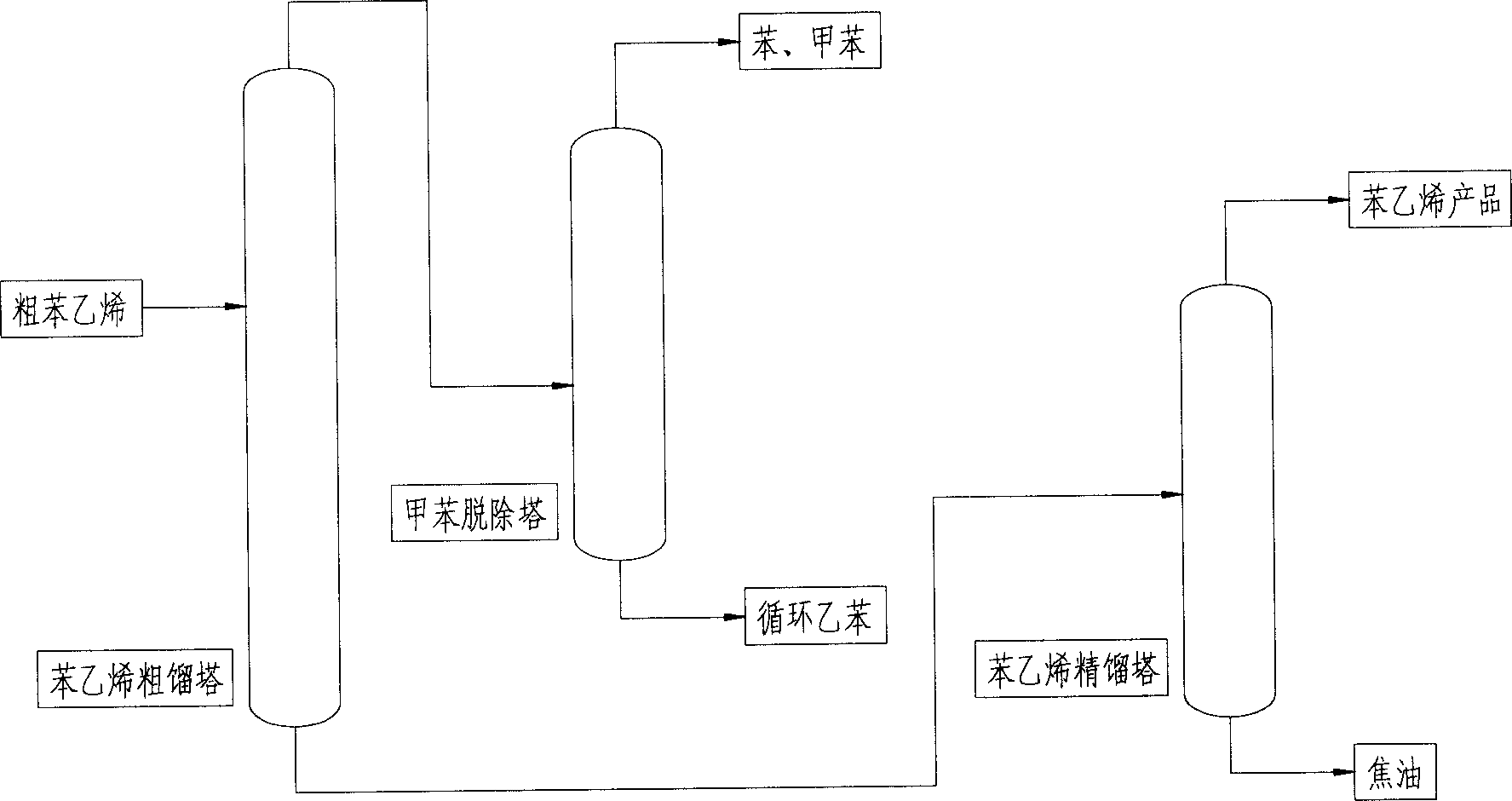
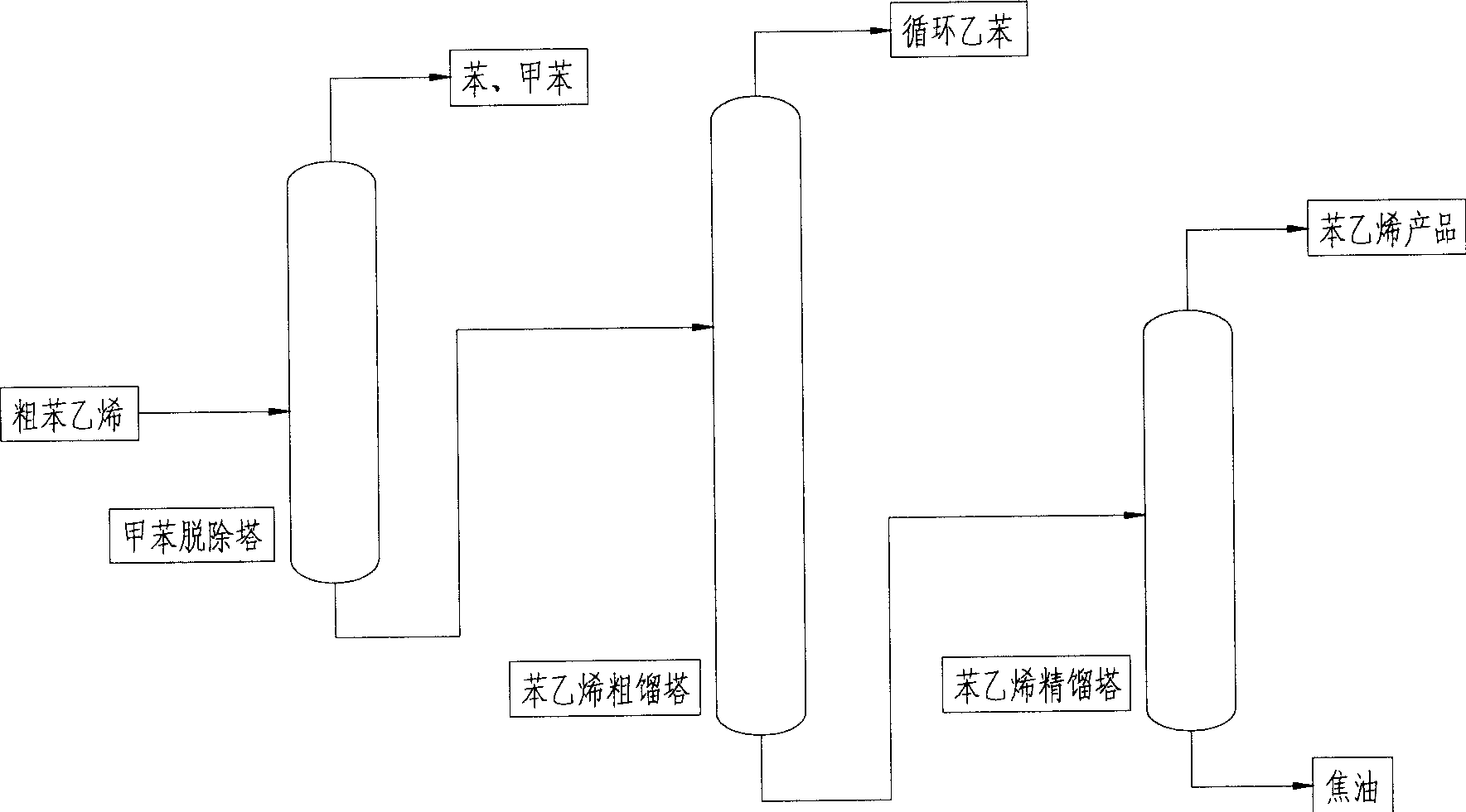
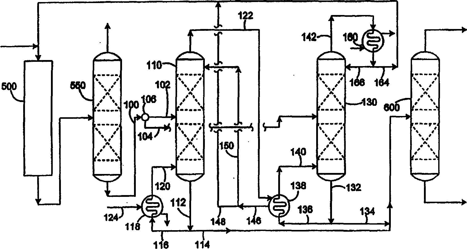
The invention relates to technique for styrene separation. Wherein, using transform heat integration technique to separate ethylbenzene/styrene, dividing common single tower into two towers of C101A with higher pressure and C101B with lower pressure; putting coarse raw material into C101B tower, drawing material from side line of C101B tower as feed to C101A; using gas phase on C101A top to heat directly liquid on bottom of C101B; heating just to C101A bottom; the ethylbenzene on top of C101A can de recycled without detoluening operation, but the material on top of C101B needs for detoluening operation on C102 tower. Compared with traditional technique, this invention can decrease energy consumption 40-50%.
Description
technical field [0001] The invention relates to a process for separating styrene, which uses a pressure-swing heat integration process to separate ethylbenzene / styrene, and divides an ordinary ethylbenzene / styrene separation tower (single tower) into two towers (C101A, B) for operation, and C101A The operating pressure of the tower is relatively high, and the operating pressure of the C101B tower is low. The gas phase at the top of the C101A tower is directly used to heat the liquid at the bottom of the C101B tower. Of the two towers C101A and B, only the bottom of the C101A tower needs steam (or other heat sources) for heating. Only the C101B tower is fed, and the C101A tower is fed from the side line of the C101B tower. Benzene and toluene are all removed from the top of the C101B tower. The technological process is simple, and compared with the traditional single-tower ethylbenzene / styrene separation tower, this technological method can significantly reduce the energy consu...
Claims
Login to View More Application Information
Patent Timeline
 IPC IPC(8): C07C15/16C07C7/00C07C7/04
Inventor 蓝仁水黄贵明
Owner 蓝仁水