Defroster of refrigerant circuit and rotary compressor

A rotary compressor and compression unit technology, which is applied in the field of the defrosting device of the refrigerant circuit and the rotary compressor used in the refrigerant circuit, can solve problems such as difficult to determine where to insert, faults in the action, performance degradation, etc., and achieve rapid Evaporator defrosting, the effect of reducing production costs

Inactive Publication Date: 2006-02-22
SANYO ELECTRIC CO LTD
View PDF0 Cites 5 Cited by
  • Summary
  • Abstract
  • Description
  • Claims
  • Application Information

AI Technical Summary

Problems solved by technology

For this reason, in the past, the pin was fixed to the cylinder by pressing it into the spring hole, but this pressing deformed the protrusion of the cylinder, creating a gap with the support member (bearing) that blocked the opening surface of the cylinder, and it was not possible to secure the inside of the cylinder. The hermeticity, resulting in performance degradation such problems
[0012] Therefore, for example, if the outer diameter of the pin is smaller than the inner diameter of the spring hole to prevent deformation of the cylinder (in this case, it is necessary to prevent the pin from coming out of the airtight container), then the rotary compressor stops and the high-pressure side in the cylinder is closed. When the pressure drops, the intermediate pressure in the airtight container pushes the pin to the spring side, causing the spring to be crushed and malfunctioning of the operation.
[0013] On the other hand, for example, when the outer diameter of the pin is larger than the inner diameter of the spring hole to the extent that the cylinder does not deform, there is a problem that it is difficult to determine where the pin should be inserted in the process of pressing the pin into the spring hole.

Method used


Image

  • Defroster of refrigerant circuit and rotary compressor
  • Defroster of refrigerant circuit and rotary compressor
  • Defroster of refrigerant circuit and rotary compressor

Examples


Embodiment Construction

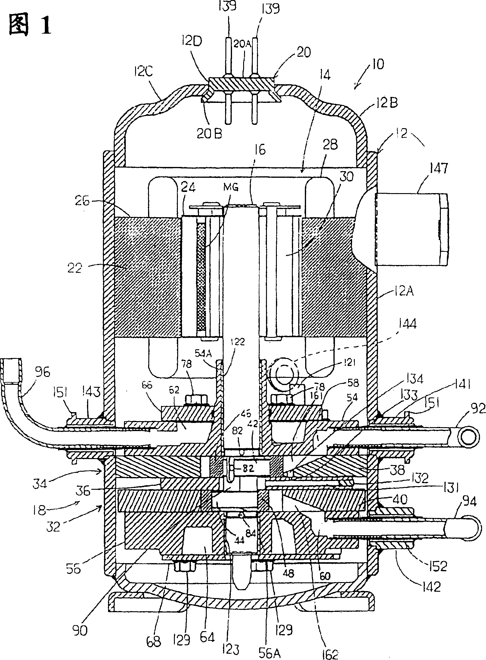
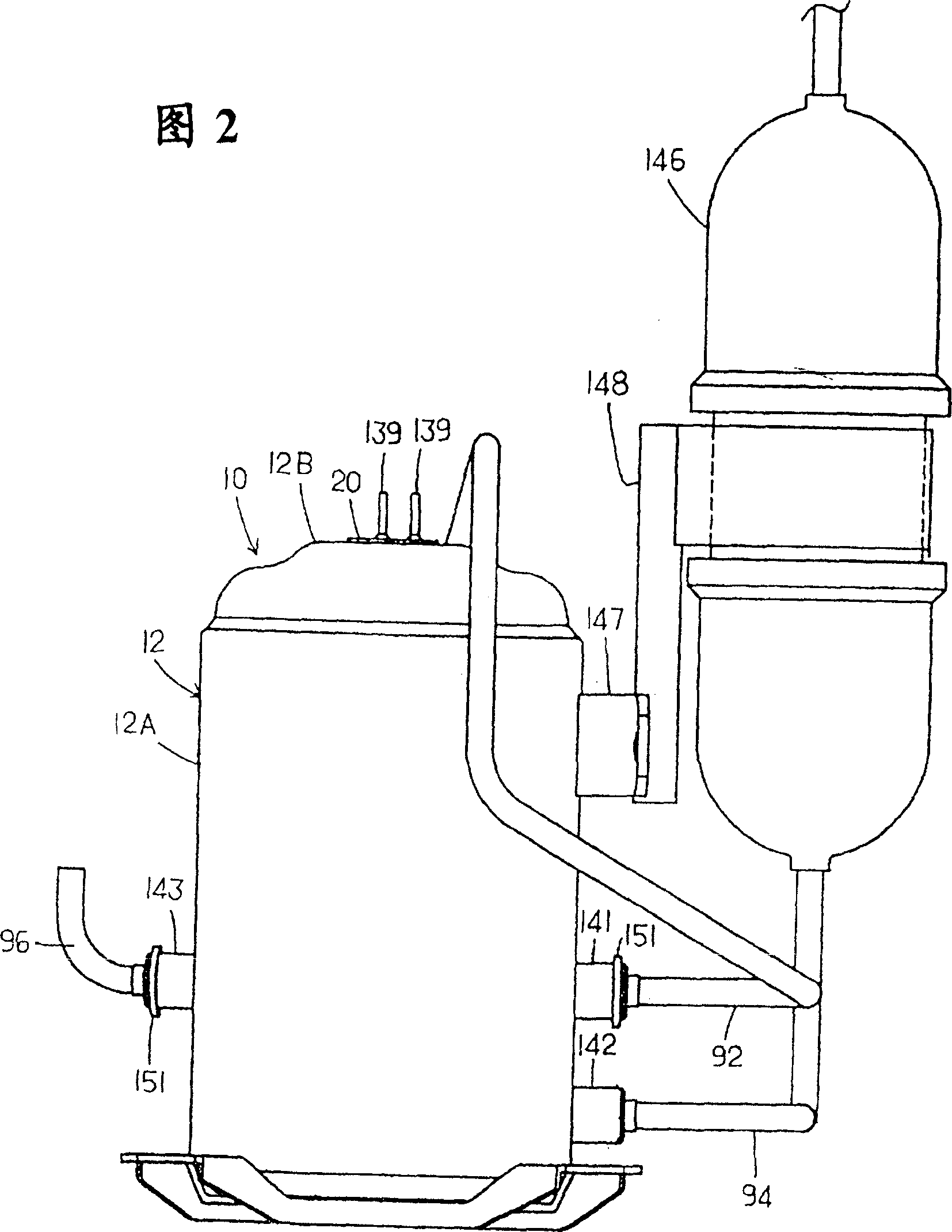
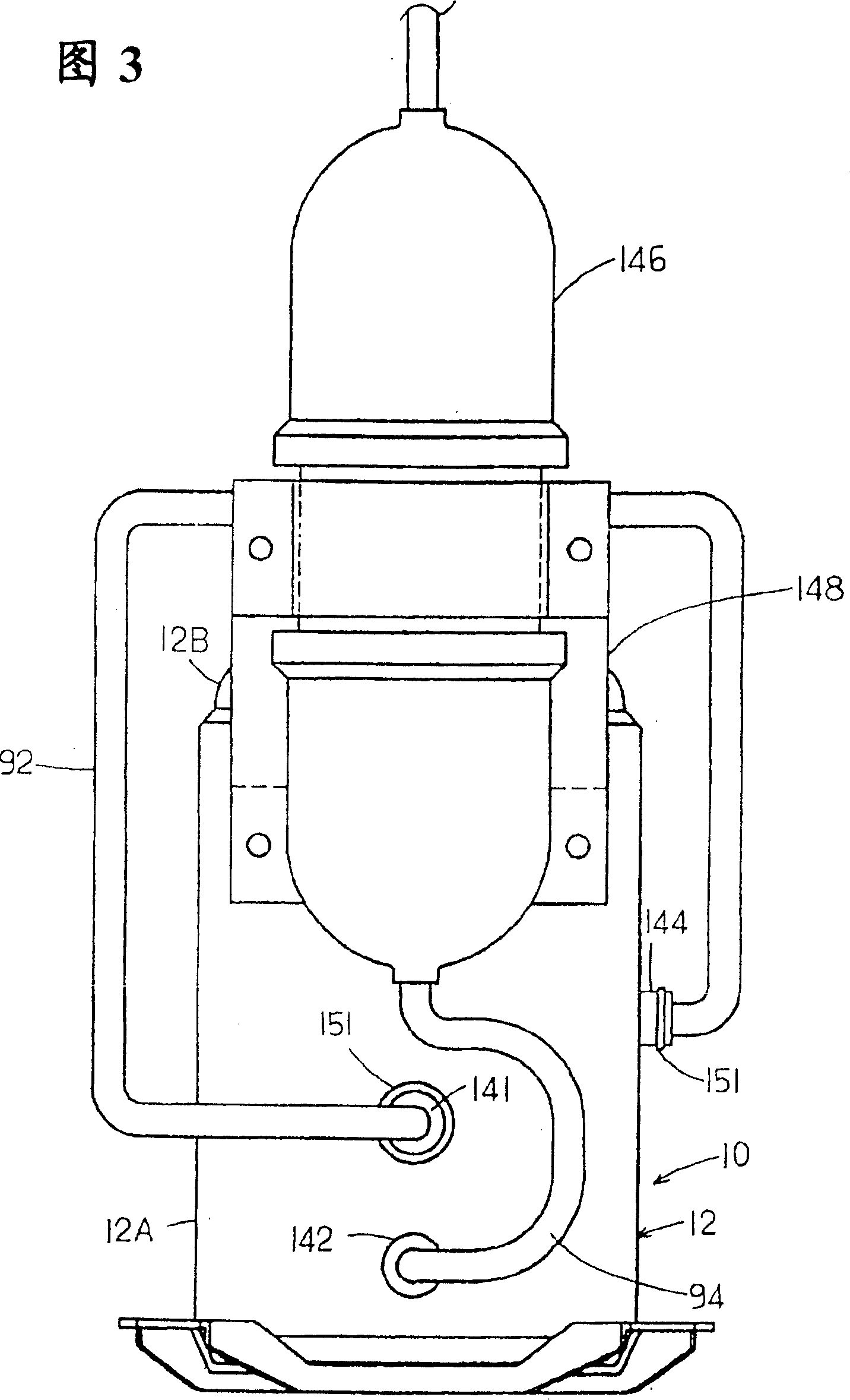
[0057] Hereinafter, embodiments of the present invention will be described in detail with reference to the drawings. 1 shows a longitudinal sectional view of an internal intermediate pressure multi-stage (two-stage) compression rotary compressor 10 having first and second rotary compression units 32, 34 as an embodiment of the rotary compressor of the present invention. FIG. 2 is a front view of the rotary compressor 10, FIG. 3 is a side view of the rotary compressor 10, and FIG. 4 is another longitudinal sectional view of the rotary compressor 10. Figure 5 is still another longitudinal sectional view of the rotary compressor 10, Image 6 7 is an enlarged sectional view of the rotary compression mechanism portion 18 of the rotary compressor 10. FIG.

[0058] In each figure, symbol 10 is carbon dioxide (CO 2 ) is an internal intermediate pressure type multi-stage compression rotary compressor used as a refrigerant. The rotary compressor 10 is composed of a cylindrical airtigh...


PUM


Abstract

The defroster of refrigerant circuit and rotary compressor includes a rotary compressor (10) that, a gas cooler (154), an expansion valve (156), and an evaporator (157). The rotary compressor (10) discharges a refrigerant gas that has been compressed by a first rotary compressing unit into a hermetic vessel, and the discharged intermediate-pressure refrigerant gas is compressed by the second rotary compressing unit. To defrost the evaporator, the refrigerant gas discharged from the second rotary compressing unit is introduced into the evaporator without decompressing it by the expansion valve. Furthermore, the refrigerant gas discharged from the first rotary compressing unit is introduced into the evaporator. At the same time, an electromotive unit of the rotary compressor is run at a predetermined number of revolutions. The inertial force of a vane at the foregoing number of revolutions is set to be smaller than the urging force of a spring. Thus, the defroster restrains a vane jump that takes place when an evaporator is defrosted in a refrigerant circuit using a so-called internal intermediate-pressure type double-stage compression rotary compressor.

Description

[0001] This application is an invention patent application filed by "Sanyo Electric Co., Ltd." on August 28, 2002 with the application number "02142298.2" and the title of the invention "Defrosting device for refrigerant circuit and rotary compressor for refrigerant circuit" divisional application. technical field [0002] The present invention relates to a defrosting device for a refrigerant circuit and a rotary compressor for the refrigerant circuit, in which a so-called internal intermediate pressure type two-stage compression rotary compressor is used. [0003] The present invention also relates to a rotary compressor, which has an electric unit and first and second rotary compression units driven by the electric unit in a closed container, and the refrigerant gas compressed by the first rotary compression unit is discharged into the airtight container, and the discharged intermediate-pressure refrigerant gas is compressed by the second rotary compression unit. Backgroun...

Claims


Application Information

Patent Timeline
Patent Type & Authority Applications(China)
IPC IPC(8): F04C23/00F04C18/356F25B47/02F01C21/08F04C28/00F04C28/08F04C29/02F04C29/04F25B1/10F25B9/00F25B31/02
CPCF04C2210/1027F25B1/10F04C28/08F04C2210/1072F01C21/0809F25B9/008F04C23/001F25B2309/061F04C18/3562F01C21/0863F04C29/023F04C23/008F25B31/026F01C21/0845F25B47/022F04C23/00
Inventor 山崎晴久只野昌也松本兼三里和哉松浦大斋藤隆泰
Owner SANYO ELECTRIC CO LTD
Why Eureka
Try Eureka