Supercharge Your Innovation With Domain-Expert AI Agents!

Valve travel indicator

A technology of indicator and valve stroke, applied in valve device, thin material handling, transportation and packaging, etc., can solve problems such as manual periodic inspection, and achieve the effect of reducing manufacturing cost

Active Publication Date: 2006-02-22
FISHER CONTROLS INT LLC
View PDF0 Cites 5 Cited by
  • Summary
  • Abstract
  • Description
  • Claims
  • Application Information

AI Technical Summary

Problems solved by technology

As a result, many of these valves can only be inspected by humans at regular intervals, for example, once a year, or while valve operation problems are being addressed

Method used


Image

  • Valve travel indicator
  • Valve travel indicator
  • Valve travel indicator

Examples


Embodiment Construction

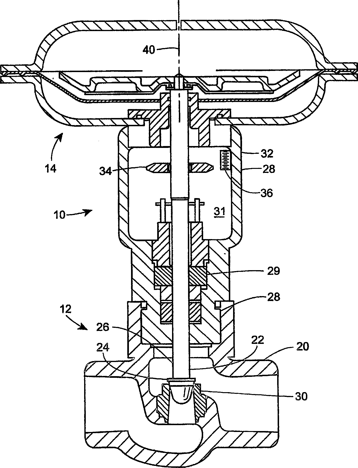
[0010] figure 1 is a cross-sectional view illustrating a control valve assembly 10 according to one embodiment of the present invention. Control valve assembly 10 may include valve 12 and actuator 14 (partially shown).

[0011] Valve 12 may include a valve body 20 and a movable operator 22 including a valve plug 24 connected to a valve stem 26 to control the flow of materials such as liquids and gases. Furthermore, the valve body 20 includes a valve packing box 28 and a valve packing 29 to establish a fluid-tight and guiding surface for the valve stem 26 . As is known to those skilled in the art, valve stems are typically polished to a finish of approximately 4 microns Ra (arithmetic mean) to reduce valve packing damage and increase control valve assembly life.

[0012] The valve stem 26 is mechanically connected to (not shown) an actuator 14 which applies an axial force to the valve stem 26 to control the relative position of the valve plug 24 with respect to the valve seat...


PUM


Abstract

A valve travel indicator is described. An indicator portion (34) indicates a location on a valve indicator scale (36). A retaining portion is fixedly coupled to the indicator portion (34) and movably coupled to a valve stem (26). The retaining portion fixedly couples the indicator portion (34) to the valve stem (26) during movement of the valve stem and movably couples the indicator portion (34) to the valve stem (26) in response to a predetermined force level exerted upon the indicator portion (34).

Description

technical field [0001] This invention relates generally to valves and, more particularly, to valve travel indicators. Background technique [0002] In many industries, valves are used to control the flow of liquids and gases. Many valves are automated so that the valve can be opened and closed from a remote location, for example by a computer control system. Consequently, many of these valves can only be manually inspected periodically, for example, once a year or while valve operation problems are being resolved. Valve travel indicators have been used in many valve systems to indicate whether a valve is open, closed or partially open. These valve travel indicators are typically located on the open portion of the yoke used to connect the valve to a control mechanism such as an actuator. Contents of the invention [0003] According to one embodiment of the invention, a valve travel indicator in combination with a control valve is described. The valve travel indicator in...

Claims


Application Information

Patent Timeline
Patent Type & Authority Applications(China)
IPC IPC(8): F16K37/00
CPCY10T137/8292F16K37/0016
Inventor 迈克尔·K·洛弗尔
Owner FISHER CONTROLS INT LLC
Features
  • R&D
  • Intellectual Property
  • Life Sciences
  • Materials
  • Tech Scout
  • Unparalleled Data Quality
  • Higher Quality Content
  • 60% Fewer Hallucinations
Learn More