Cutting knife angle-adjusting method

A technology for adjusting angles and cutting knives, applied to fine working devices, stone processing equipment, manufacturing tools, etc., can solve the problems of time-consuming adjustment, error-prone, and affecting the production capacity of line-drawing mechanisms, etc.

Inactive Publication Date: 2006-03-08
IND TECH RES INST
View PDF0 Cites 4 Cited by
  • Summary
  • Abstract
  • Description
  • Claims
  • Application Information

AI Technical Summary

Problems solved by technology

[0004] However, the above-mentioned traditional method of adjusting the angle and position of the cutting blade of the cutting knife relies on the worker's own experience. Whether the adjusted precision is good or not depends entirely on the worker's own experience and adjustment skills. Therefore, The traditional adjustment method is not only easy to produce errors, but also easy to cause a waste of adjustment time, relatively affecting the production capacity of the line drawing mechanism, which is not very ideal

Method used


Image

  • Cutting knife angle-adjusting method
  • Cutting knife angle-adjusting method
  • Cutting knife angle-adjusting method

Examples


Embodiment Construction

[0033] In order to better understand the technical content of the present invention, a preferred specific embodiment is given as follows.

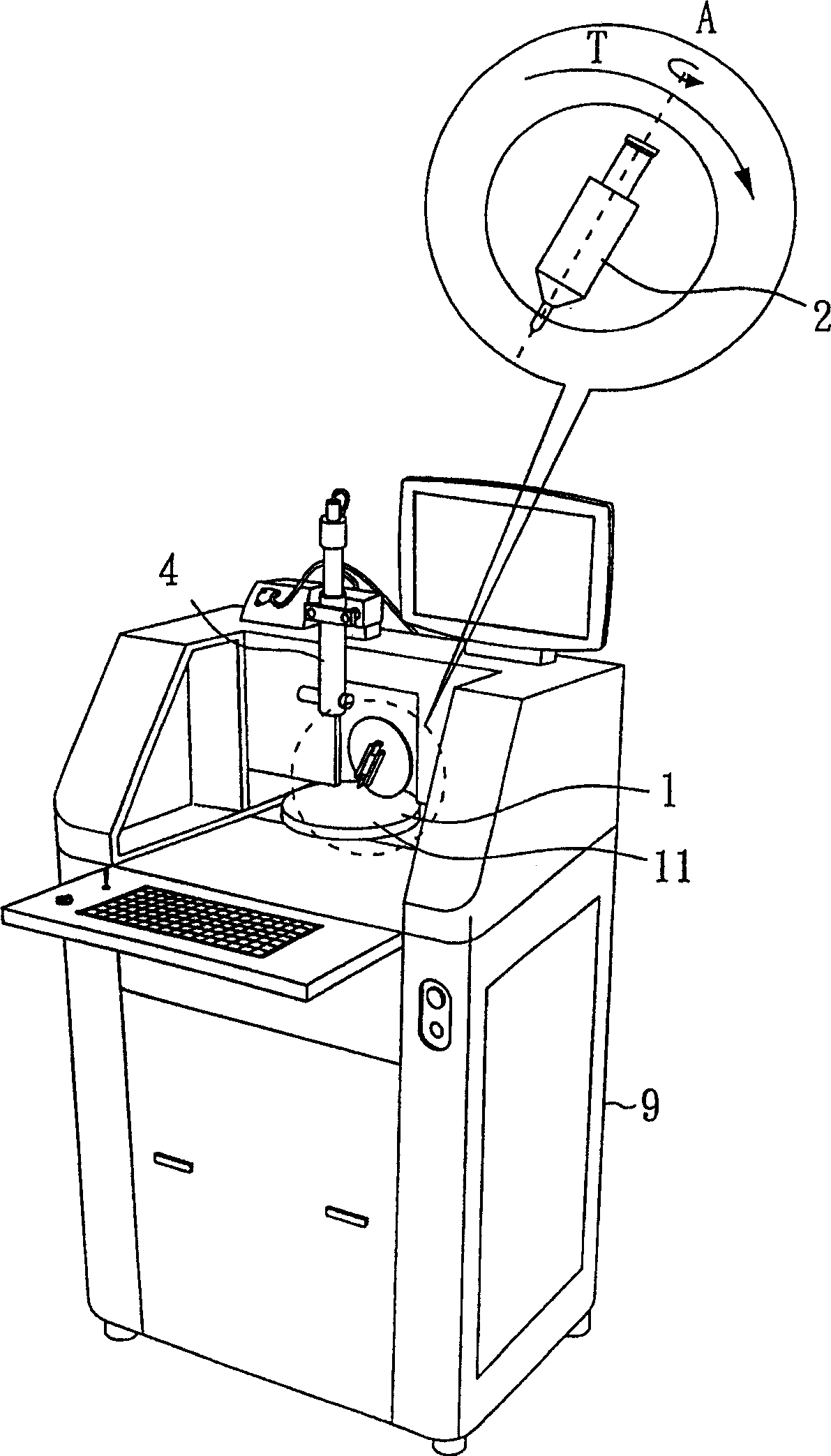
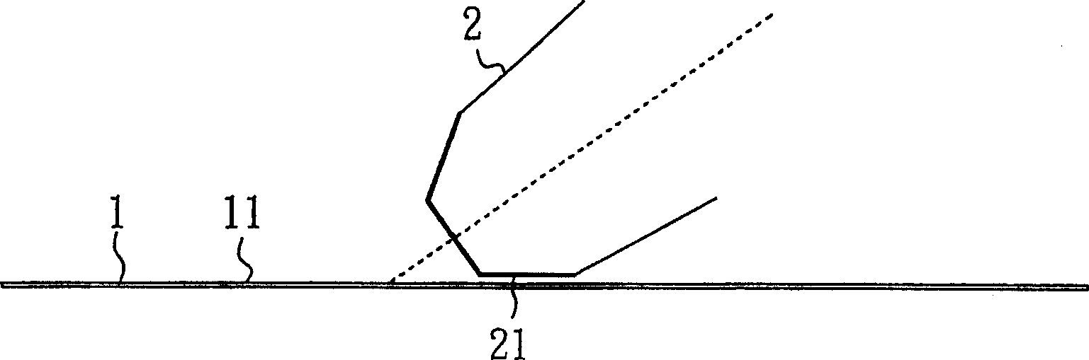
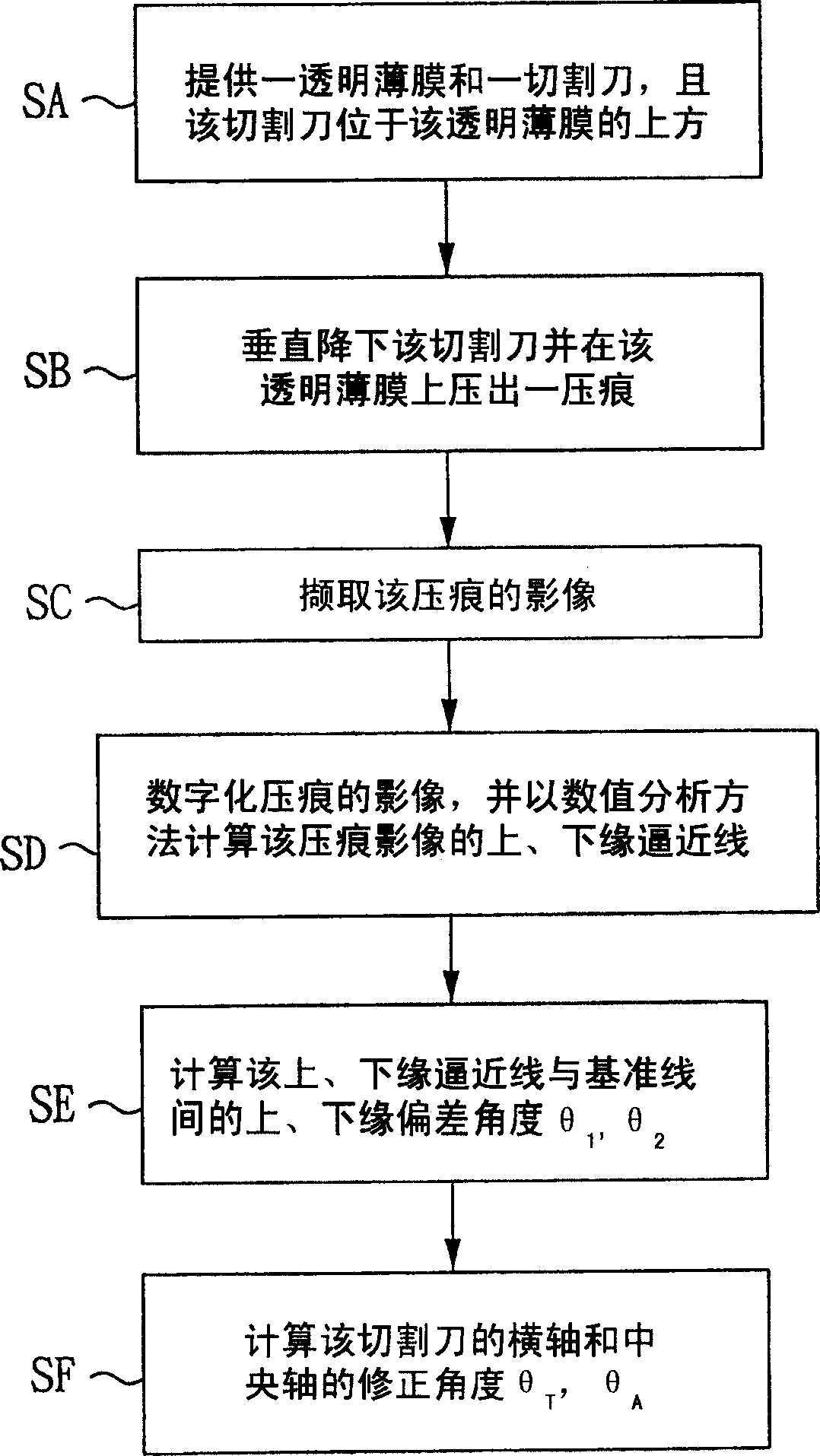
[0034] Please also see figure 1 , which is a schematic structural diagram of a preferred embodiment of the present invention; figure 2 is a schematic diagram of a cutting knife and a transparent film in a preferred embodiment of the present invention; and image 3 It is a flow chart of a preferred embodiment of the present invention, wherein a machine table 9 is shown, and a transparent film 1 (Mylar), a cutting knife 2, and an image capture device 4 are assembled on this machine table 9, wherein The cutting knife 2 is located above the transparent film 1, and the cutting knife 2 includes a central axis (A axis) and a transverse axis (T axis). In addition, the aforementioned image capture device 4 uses a CCD camera in this embodiment, and the cutting knife 2 is a diamond cutting knife in this embodiment, and the cutting knife 2 has a p...


PUM


Abstract

A adjustment angle method of cutter, before the cutter pushing broach, make the blade of the cutter create a impression on transparent film, then catch the image of the impression, then automatically calculate and regulate the angle and position of the cutter using numerical analysis and preset formula, and also can repeat the above procedure, repeat the calculation and regulation above to get exact angle and position of the cutter, so as to obtain a level and uniform impression.

Description

technical field [0001] The invention relates to a method for adjusting the angle of a cutting knife, in particular to a method for adjusting the angle of a cutting knife suitable for a line-drawing mechanism for separating brittle materials. Background technique [0002] In the general line-drawing mechanism for separating brittle materials, such as the line-drawing machine for wafers, it mainly uses a cutting knife (such as a diamond cutting knife) to carry out the line-drawing operation, and the cutting knife includes a cutting edge, which is used to place the cutting edge on the wafer. Line drawing can be performed by performing the so-called pressing knife. [0003] In addition, the cutting edge of the cutting knife must be adjusted to the desired angle and position before the line drawing operation, so as to obtain good cutting marks (such as Figure 8E shown), otherwise the cutting marks are prone to deflection at an angle or uneven width (such as Figure 8A to Figure...

Claims


Application Information

Patent Timeline
Patent Type & Authority Applications(China)
IPC IPC(8): B28D5/00
Inventor 陈贵荣谭子陵赖志一陈孟群
Owner IND TECH RES INST
Why Eureka
Try Eureka