Driving road-condition real-time recording method and its vehicular recording instrument

A vehicle-mounted recorder and real-time recording technology, applied to time registers, instruments, registration/indication, etc., can solve the problems of unstable work, single function, and high cost, and achieve simple operation, reasonable technical structure, and low manufacturing cost. Effect

Inactive Publication Date: 2006-03-08
耿军
View PDF0 Cites 25 Cited by
  • Summary
  • Abstract
  • Description
  • Claims
  • Application Information

AI Technical Summary

Problems solved by technology

In order to achieve this purpose, there have been devices for recording road conditions, but due to technical and structural reasons, most o

Method used


Image

  • Driving road-condition real-time recording method and its vehicular recording instrument
  • Driving road-condition real-time recording method and its vehicular recording instrument
  • Driving road-condition real-time recording method and its vehicular recording instrument

Examples


Embodiment Construction

[0039] The present invention will be further described below in conjunction with the accompanying drawings

[0040] host (see Figure 9 ): interior rearview mirror with TFT display (with a camera inside).

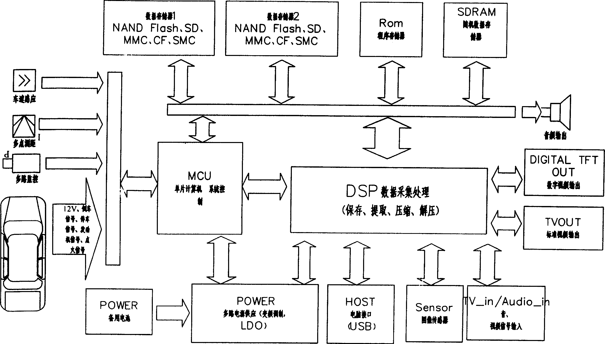
[0041] The system uses brake signal, engine signal, reversing signal, ignition switch to control the action of the system. These signals are taken from the inside of the vehicle, and the signals are introduced into the relevant IO ports of the MCU (U6) through the connection ports J7 and J8 of the system (see Image 6). U6 port function: AP: control port; PB0: running; PB1: reverse; PB2: VIDEO-IN; PB3: ignition switch; PC0: NC; PC1: browsing status; PC2: TFT switch; PDO: screen display control; PD1: LCD control; PD2: recording status detection; PD3: power status detection; PE: OSD control; PF0: DSP power control; PF1: prompt tone. Interface J7: 1: 12V-IN; 2: GROUND. Interface J8: 1: Brake; 2: Reverse; 3: Video-IN, 4: Ignition switch.

[0042] When the car starts and the...


PUM


Abstract

Pick-up head in use for monitoring load condition in real time and display screen for displaying image of load condition in real time are installed inside vehicle at proper position in the disclosed method. Through ports connected to the control system, brake signal, engine signal, reversing signal, and ignition signal are input to relevant ports of single chip, and these signals control actions of system. The control system includes MCU single chip, DSP, two pieces of data memory, ROM program memory, RAM, Sensor image sensor (pick-up head), USB interface and display screen.

Description

technical field [0001] The invention relates to a method and device for recording road conditions during the driving of a motor vehicle, and mainly refers to a real-time recording method of driving road conditions and a vehicle-mounted recorder thereof. Background technique [0002] At present, the number of motor vehicles has surged, and the accident rate has also risen sharply. There is a problem of how to accurately delineate responsibility in the process of accident handling. If the accident process can be reproduced, accurate delineation of responsibility can be achieved. In order to achieve this purpose, there have been devices for recording driving road conditions, but due to technical and structural reasons, most of them have the problems of single function, unstable work and high cost. Therefore, there is still a big gap from practical application. SUMMARY OF THE INVENTION [0003] The purpose of the present invention is to provide a real-time recording method of...

Claims


Application Information

Patent Timeline
IPC IPC(8): G07C5/00
Inventor 耿军
Owner 耿军
Why Eureka
Try Eureka