Driving road-condition real-time recording method and its vehicular recording instrument
A technology of real-time recording and road conditions, applied in the direction of time register, instrument, registration/indication, etc., can solve the problems of unstable work, single function, high cost, and achieve the effect of simple operation, reasonable technical structure and low manufacturing cost.
- Summary
- Abstract
- Description
- Claims
- Application Information
AI Technical Summary
Problems solved by technology
Method used
Image
Examples
Embodiment Construction
[0038] Below in conjunction with accompanying drawing, the present invention will be further described
[0039] host (see Figure 9 ): Interior rearview mirror with TFT display (one camera is installed inside).
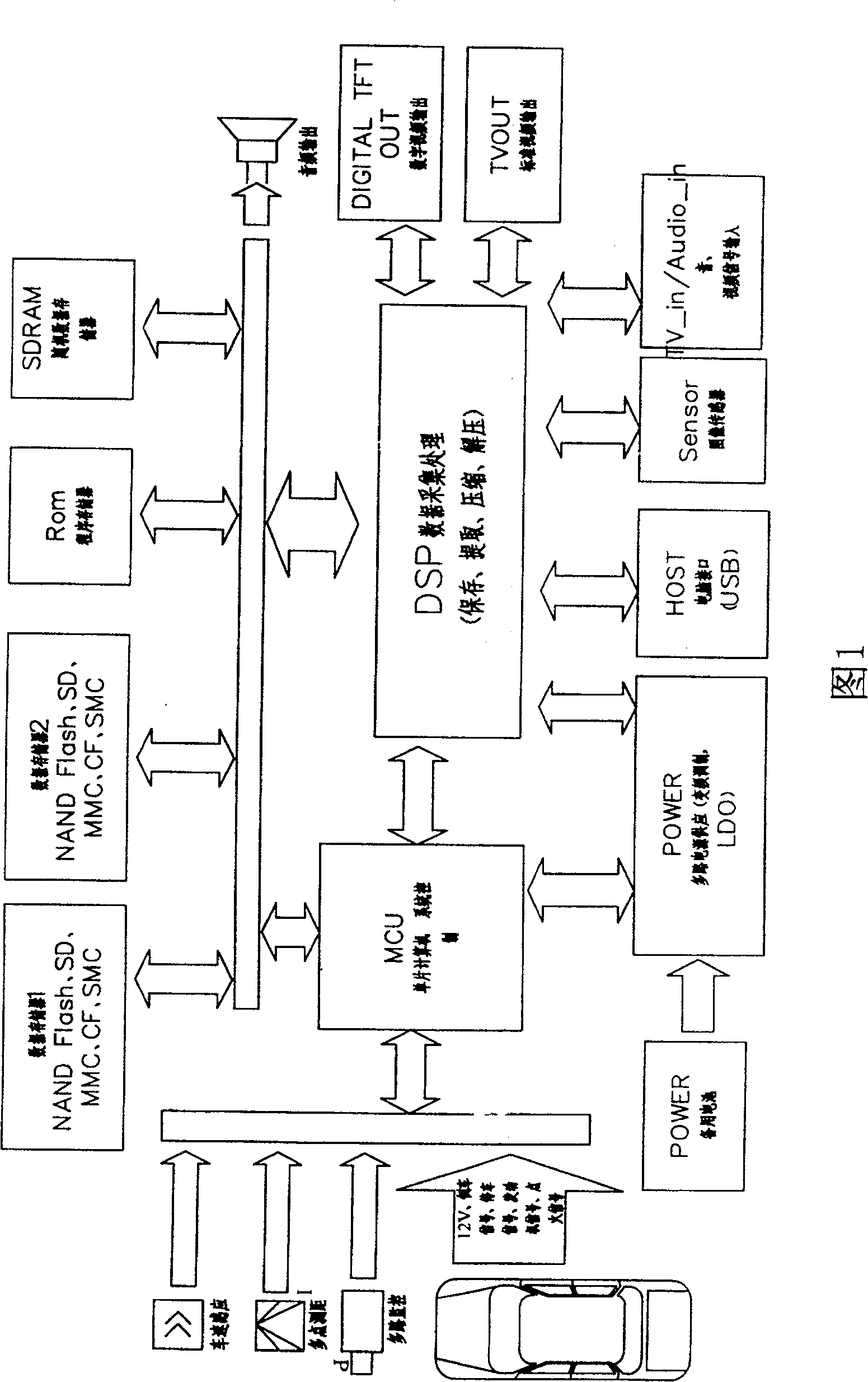
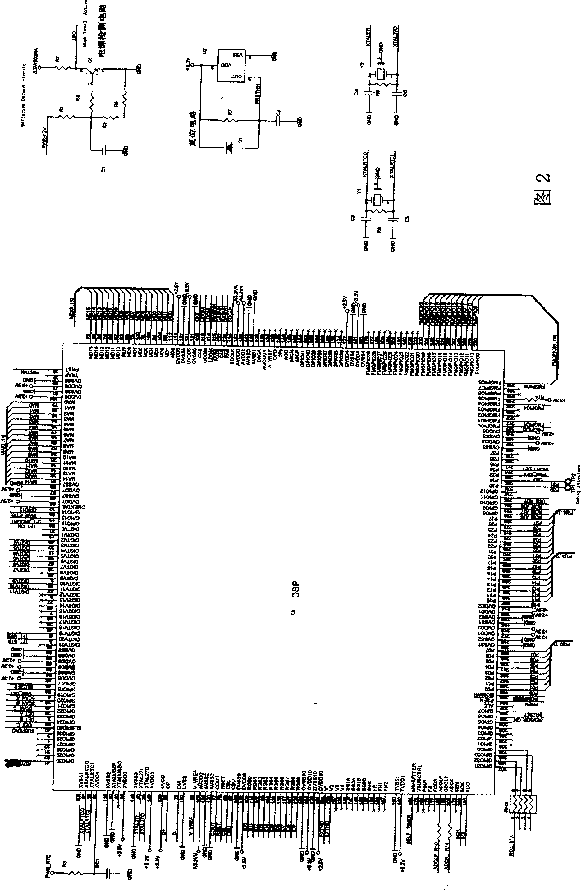
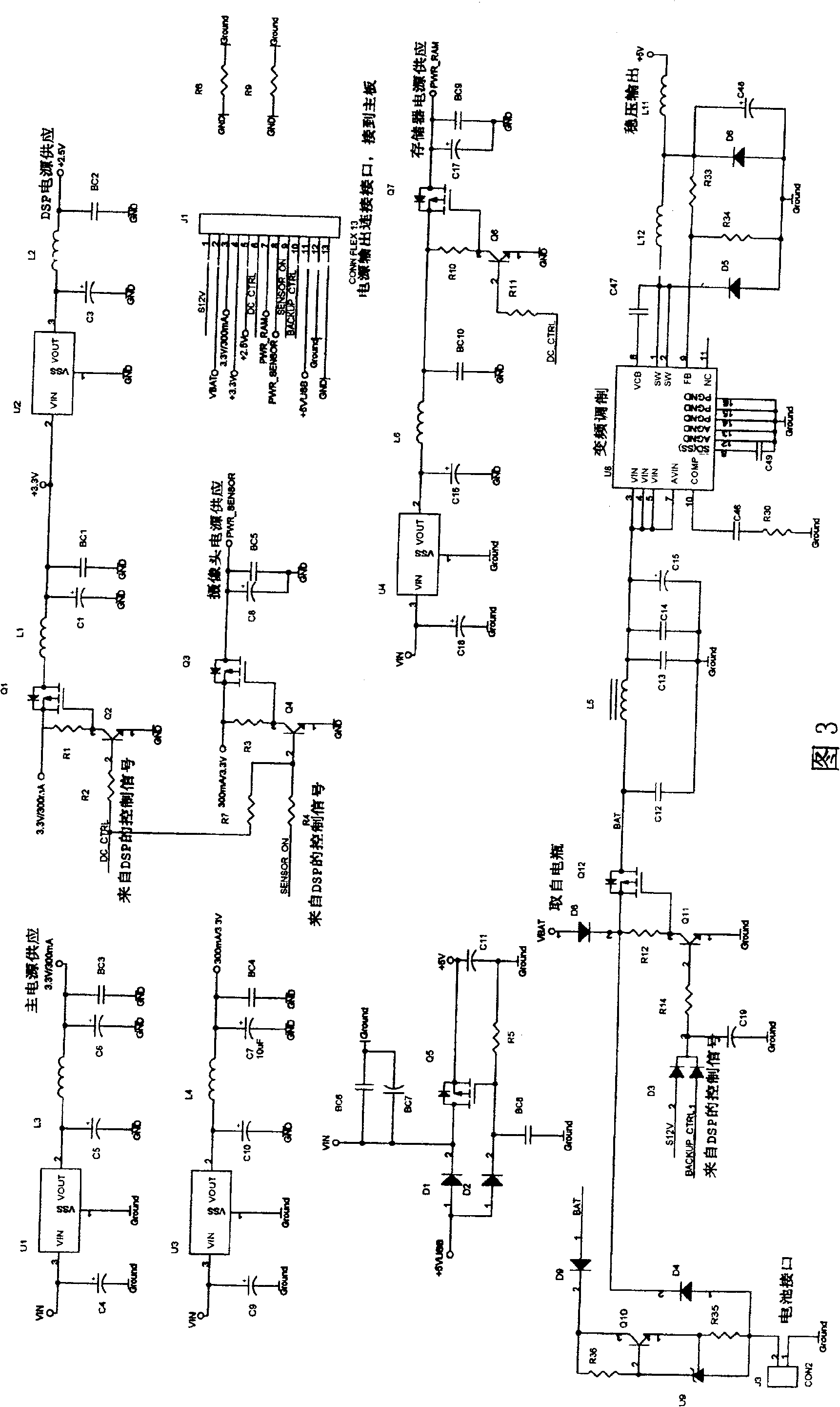
[0040] This system uses braking signal, engine signal, reversing signal, and ignition switch to control the action of the system. These signals are all taken from the inside of the vehicle, and the signals are introduced to the relevant IO ports of the MCU (U6) through the connection ports J7 and J8 of the system (see Figure 6). U6 port function: AP: control port; PB0: running; PB1: reversing; PB2: VIDEO-IN; PB3: ignition switch; PC0: NC; PC1: browsing status; PC2: TFT switch; PDO: screen display control; PD1: LCD control; PD2: recording status detection; PD3: power status detection; PE: OSD control; PF0: DSP power control; PF1: prompt tone. Interface J7: 1: 12V-IN; 2: GROUND. Interface J8: 1: Brake; 2: Reverse; 3: Video-IN, 4: Ignition switch.
[0041] When the c...
PUM
 Abstract
Description
Claims
Application Information
 - R&D
- Intellectual Property
- Life Sciences
- Materials
- Tech Scout
- Unparalleled Data Quality
- Higher Quality Content
- 60% Fewer Hallucinations
Browse by: Latest US Patents, China's latest patents, Technical Efficacy Thesaurus, Application Domain, Technology Topic, Popular Technical Reports.
© 2025 PatSnap. All rights reserved.Legal|Privacy policy|Modern Slavery Act Transparency Statement|Sitemap|About US| Contact US: help@patsnap.com


