Magnetron cooling fin

A heat sink and magnetron technology, applied in discharge tubes, microwave heating, time-of-flight electron tubes, etc., can solve problems such as limited heat transfer area of ​​heat sinks and limited cooling efficiency

Inactive Publication Date: 2006-03-08
LG ELECTRONICS INC
View PDF0 Cites 12 Cited by
  • Summary
  • Abstract
  • Description
  • Claims
  • Application Information

AI Technical Summary

Problems solved by technology

However, if a compact anode structure is required for a magnetron having the same output, there is a problem that improvement in cooling efficiency will be limited due to the limited heat transfer area of ​​the heat sink

Method used


Image

  • Magnetron cooling fin
  • Magnetron cooling fin
  • Magnetron cooling fin

Examples


Embodiment Construction

[0023] The magnetron heat sink according to a preferred embodiment of the present invention will be described in detail below with reference to the accompanying drawings.

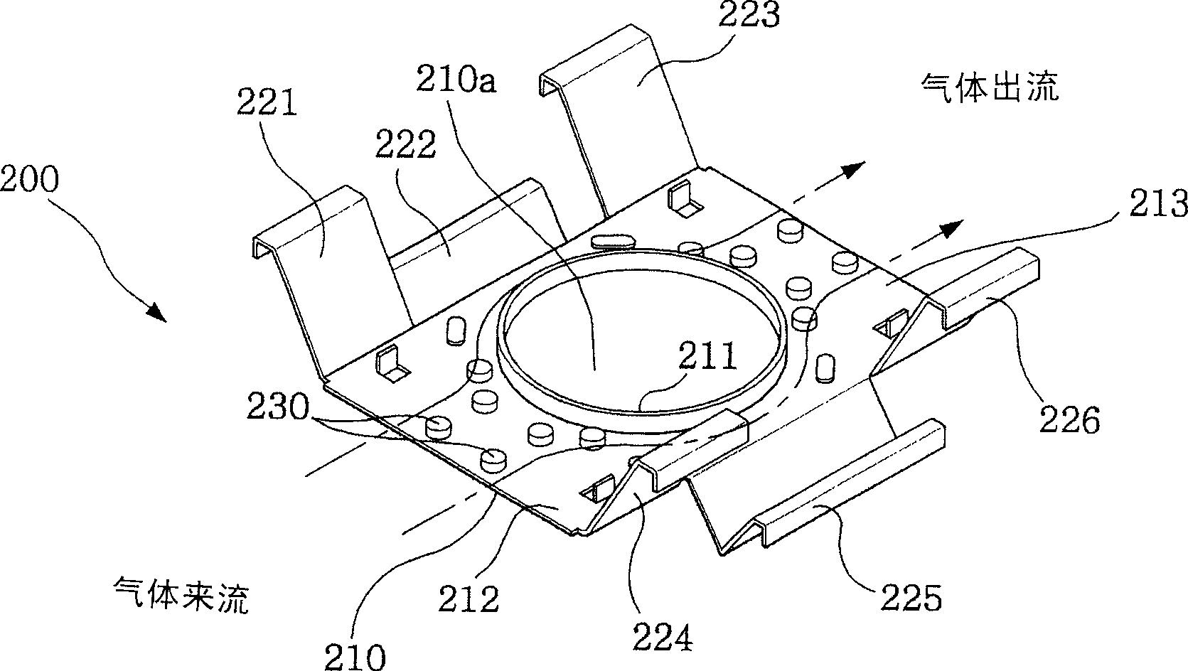
[0024] refer to image 3 , the magnetron cooling fin 200 according to the present invention comprises: a planar body 210, which has a flange-shaped through hole 210a through which the anode passes and is connected in the through hole 210a; a plurality of connection parts 221, 222 , 223, 224, 225 and 226, the connecting member extends outwards and bends at the edge of the flat body 210; One side of the planar body 210 protrudes.

[0025] Preferably, in the thus configured magnetron heat sink according to the present invention, the turbulence-promoting protrusions 230 protrude in the same direction as the protrusions 211 protruding from the edge of the flange-type through hole 210a. .

[0026] At the same time, the turbulence-enhancing protrusions 230 are set to satisfy the relationship P / H=1-10, wherein P...


PUM


Abstract

A magnetron cooling fin is disclosed, characterized in that a plurality of turbulence-promoting protrusions are provided on one side of a planar body that has a boss-type through-hole in which an anode is coupled and a plurality of coupling pieces outwardly extending and bent at edges of the planar body, whereby, with inflow air undergoing flow separation at top ends of the turbulence-promoting protrusions and coming again into contact with the planar body, an existing temperature boundary gets thinned and a friction coefficient gets increased, thereby improving a heat transfer rate and an cooling efficiency.

Description

technical field [0001] The present invention relates to a magnetron heat sink, and in particular to a magnetron heat sink configured to have an enlarged heat exchange area so as to improve cooling efficiency. Background technique [0002] Generally, a magnetron is used as a heat source for heating an object by releasing electrons from the cathode through an electromagnetic field to generate radio frequency energy at about 2450 megahertz (MHz) when energized through the cathode, and then outputting the generated energy through an antenna. This magnetron includes an anode unit 10, a cathode unit 20 and a magnet unit 30, such as figure 1 shown. [0003] The anode unit 10 includes an anode cylinder 11 and a plurality of vanes 12 radially formed on the inner surface of the anode cylinder 11 . The cathode unit 20 includes a filament 21 , end shields 22 and 23 , a center wire 24 and a side wire 25 . The filament 21 has a helical structure made of an alloy material containing, fo...

Claims


Application Information

Patent Timeline
Patent Type & Authority Applications(China)
IPC IPC(8): H01J23/033H01J23/00
CPCH01L2924/0002H05B6/72H01J23/005H01L2924/00H01J23/16
Inventor 李钟寿李容戍
Owner LG ELECTRONICS INC
Why Eureka
Try Eureka