
Imaging method and imaging apparatus

一种成像方法、成像设备的技术,应用在图像通信、电视、彩色电视等方向,能够解决难有效的操作、不能获得聚焦变换、不能自动改变成像方向和区域等问题,达到平滑转换的效果

Inactive Publication Date: 2006-03-08
SONY CORP
View PDF2 Cites 3 Cited by
  • Summary
  • Abstract
  • Description
  • Claims
  • Application Information

AI Technical Summary

Problems solved by technology

[0005] However, in situations where there are multiple objects in a photo with different light sources, for example, in an image that includes an outdoor object outside a window when a photo is taken indoors, the white point can only be compared with the specific The light source (either indoor or outdoor) is the same, so the image may not be picked up smoothly
[0006] Furthermore, in Patent Document 1, since the transition between two points can only be performed at a fixed rate, it is difficult to perform an efficient operation such as "terminating when smoothly decreasing the transition rate immediately before its end convert"
[0007] Furthermore, in Patent Document 1, in the case of further implementing zoom transition, if the focus transition is linearly interpolated from the start point to the end point with respect to the inner focus lens in a simple manner, the intended focus transition may not be obtained, and may not be accompanied by The transformations described above together automatically change the imaging direction and area

Method used


Image

  • Imaging method and imaging apparatus
  • Imaging method and imaging apparatus
  • Imaging method and imaging apparatus

Examples


Embodiment Construction

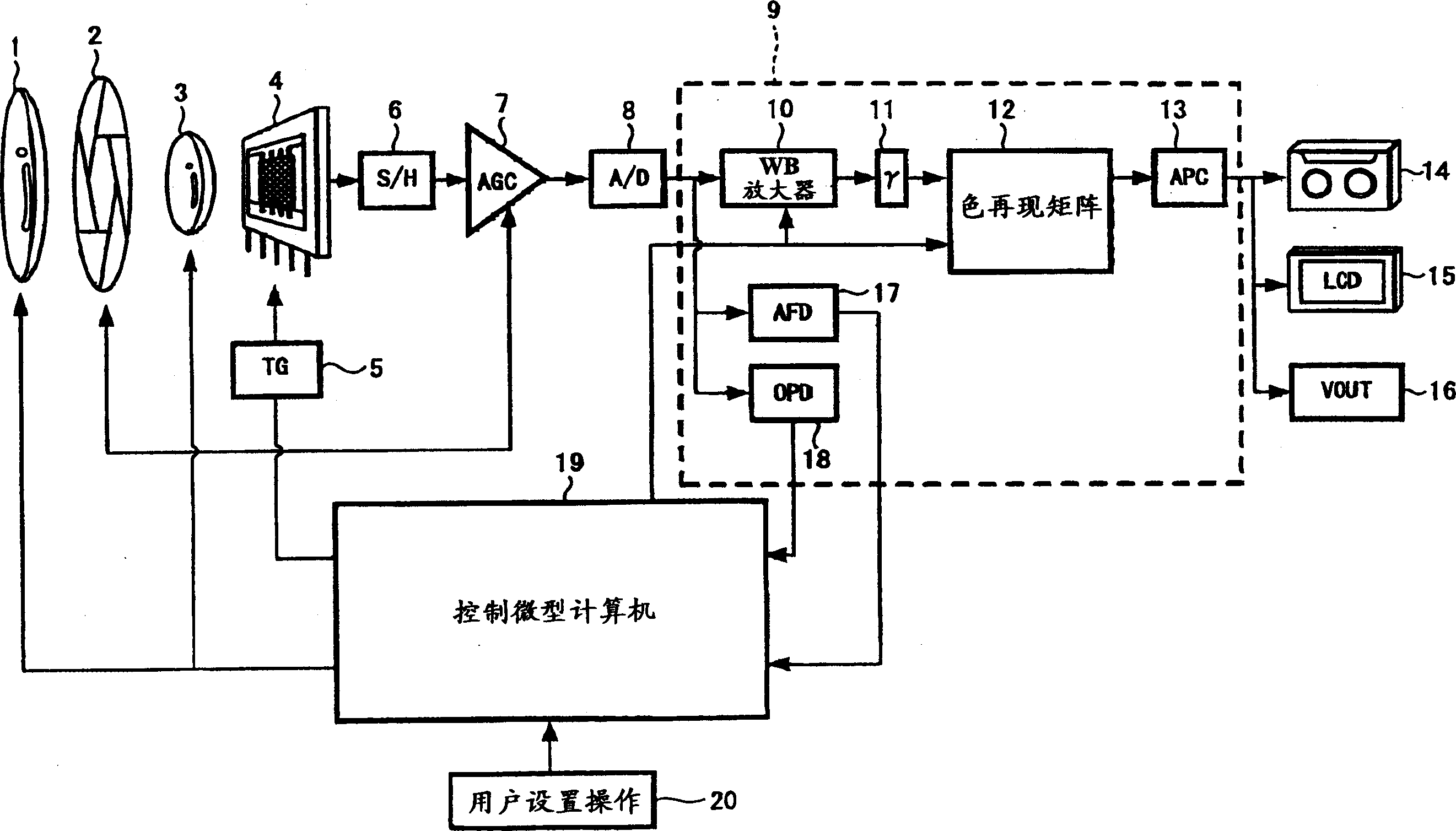
[0039] figure 1 Shown is an example of an image forming apparatus according to an embodiment of the present invention.

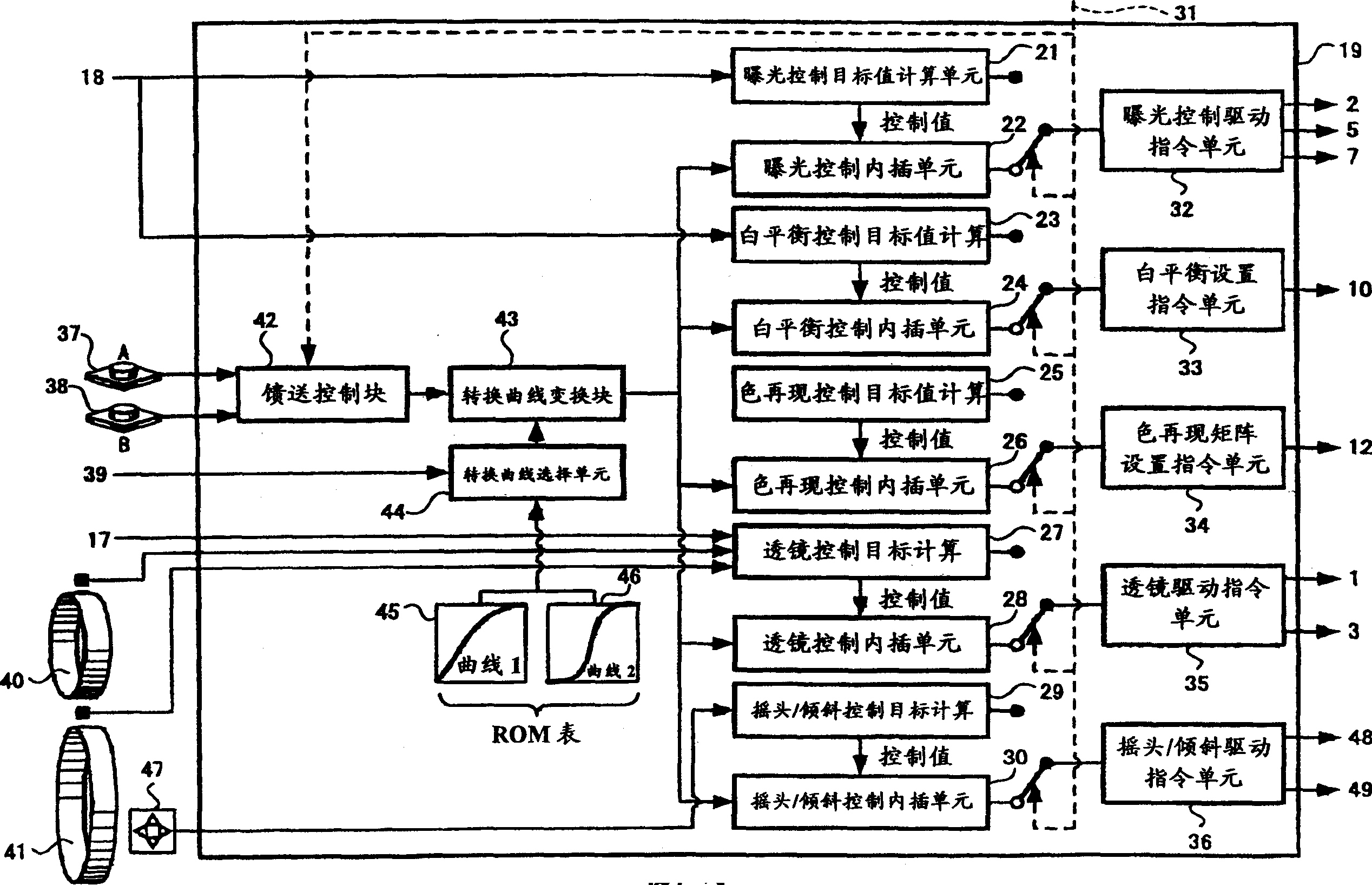
[0040] figure 1 is to show in a simplified manner the structure of the relevant parts of the imaging device according to the embodiment of the present invention, which includes: optical system zoom lens 1; aperture 2; focusing lens 3; image pickup device 4; timing generator (TG) 5; / H (sample / hold) 6; AGC (automatic gain control) circuit 7; A / D (analog / digital) conversion circuit 8; white balance amplifier 10 (hereinafter referred to as WB amplifier), gamma correction circuit 11, color reproduction Matrix 12, aperture circuit 13, auto focus detector 17 and auto exposure (AE) detector 18 included in signal processing block 9; camera control microcomputer 19; recording medium 14; LCD (liquid crystal display) display 15; VOUT ( video output) 16; and so on.

[0041] The image pickup device 4 is a CCD (Charge Coupled Device) or the like, in which a unit (pixel...


PUM


Abstract

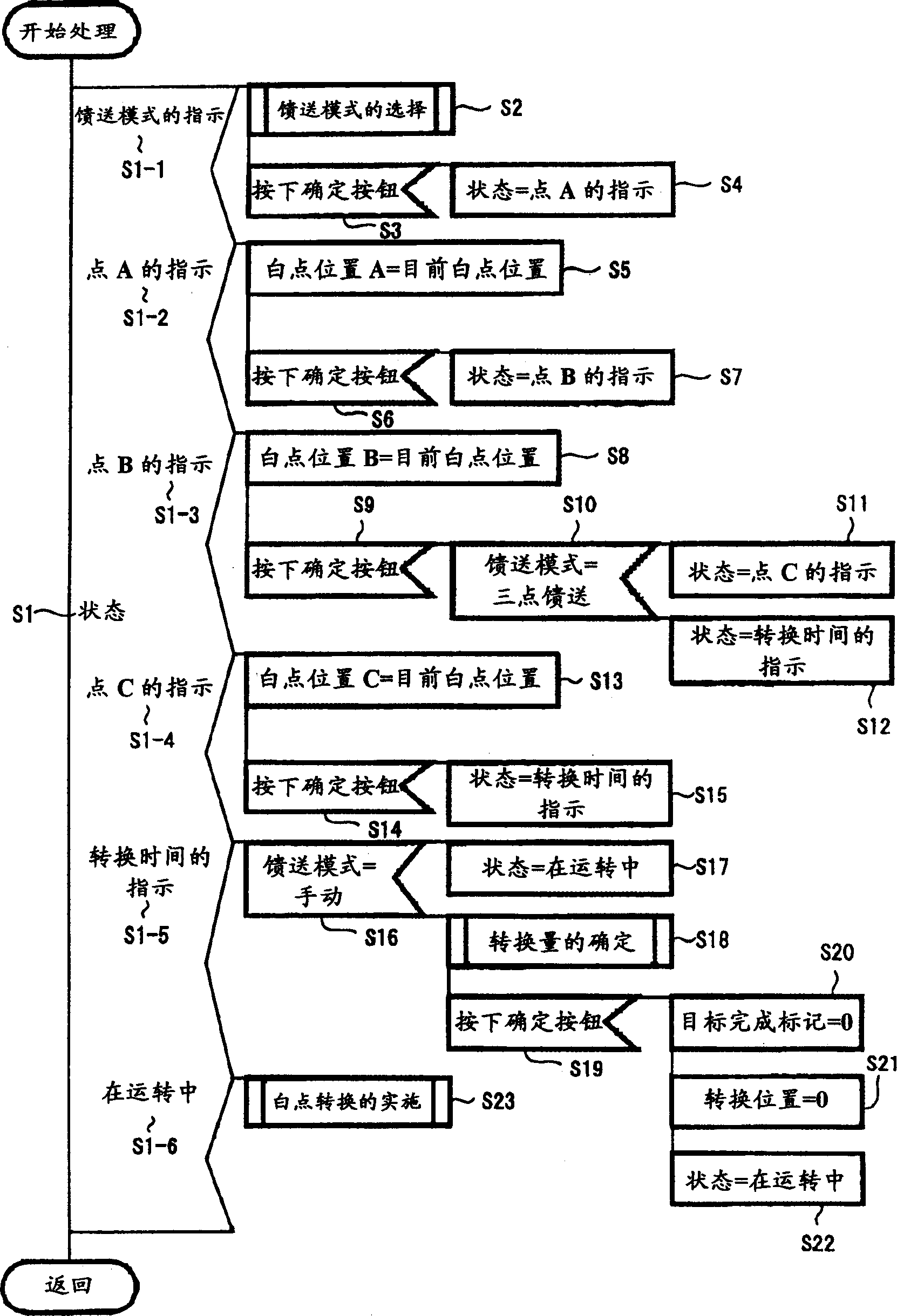
An imaging method and an imaging apparatus are provided in which information about white points determined is stored and operation is performed only between the stored white points. The imaging method includes the steps of: automatically or manually determining at least two white points (Steps S1-2, S1-3 and S1-4); storing the above described at least two white points determined (Steps S5, S8 and S13); and manually or automatically adjusting a white point with the range between the above described at least two white points stored as a white point adjustment range (Step S23).

Description

[0001] Cross References to Related Applications [0002] The present invention encompasses subject matter related to Japanese Patent Application JP2004-254783 filed in the Japan Patent Office on Sep. 1, 2004, the entire contents of which are hereby incorporated by reference. technical field [0003] The invention relates to an imaging method and an imaging device, which include a white balance function, a color adjustment function, and a function capable of changing zoom setting, camera imaging direction and camera imaging area. Background technique [0004] For example, in the case of capturing an image of an object with a consumer video camera, it is in the art to capture the image so that an automatic white balance function is used to align the white point with the light source in the imaging environment. [0005] However, in situations where there are multiple objects in a photo with different light sources, for example, in an image that includes an outdoor object outsid...

Claims


Application Information

Patent Timeline
Patent Type & Authority Applications(China)
IPC IPC(8): H04N5/235H04N5/232G03B3/00G03B7/08H04N23/40G02B7/08
CPCH04N9/735H04N23/88
Inventor 伊藤正信宇根英辅杉本岳夫栉田英功熊木甚洋
Owner SONY CORP
Learn More