Sleeve for a printing cylinder and the printing cylinder

A technology of printing presses and cylinders, which is applied to the general parts of printing machinery, printing machines, rotary printing machines, etc., can solve the problem of high storage costs, and achieve the effect of low storage costs and low manufacturing costs

Inactive Publication Date: 2006-03-15
MANROLANAD AG
View PDF1 Cites 3 Cited by
  • Summary
  • Abstract
  • Description
  • Claims
  • Application Information

AI Technical Summary

Problems solved by technology

Storage costs are high as the entire four-ply sleeve must be removed from the press cylinder

Method used


Image

  • Sleeve for a printing cylinder and the printing cylinder
  • Sleeve for a printing cylinder and the printing cylinder
  • Sleeve for a printing cylinder and the printing cylinder

Examples


Embodiment Construction

[0016] In the following text, reference Figure 1-3 The present invention is described in more detail.

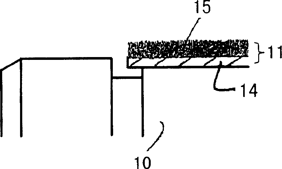
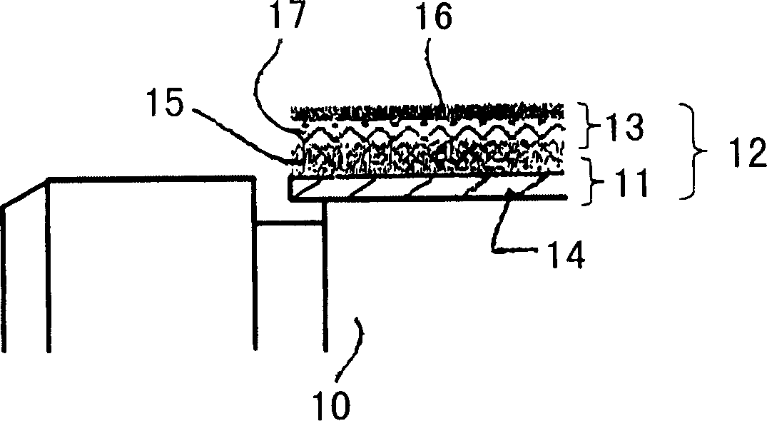
[0017] figure 1 Details of the printing press cylinder 10 (ie transfer cylinder or blanket cylinder) are shown. The basic body 11 of the sleeve, generally designated 12 , is radially adjacent to the surface of the drum 10 on the outside. Furthermore, in addition to the basic body 11, the sleeve 12 has a replaceable or replacement body 12 (cf. figure 2 ). image 3 A sleeve 12 and a drum 10 are shown, wherein the sleeve 12 includes a basic body 11 and a replaceable body 13 .

[0018] In the context of the present invention, a sleeve 12 for a cylinder 10 of a printing press is proposed, the sleeve 12 comprising a basic body 11 and a replaceable body 13 . The base body 11 is fixed and preferably permanently connected in a non-detachable manner to the cylinder 10 of the printing press. The base body 11 , which is fastened inseparably to the drum 10 , can only be detached ...


PUM


Abstract

The invention relates to a roller sleeve especially be applicable to printer transfer printing roller or rubber roller, comprising a base main body (11) with at least one layer and a replaceable main body (13) with at least one layer, wherein the base main body (11) is connected with a roller (10) of the printer, and the replaceable main body (13) can be drawn down from the base main body (11) and the roller (10) of the printer without damage, which especially is used to replace.

Description

technical field [0001] The invention relates to a sleeve for a printing press cylinder. Furthermore, the invention relates to a printing press cylinder. Background technique [0002] The sleeve and the printing press cylinder tend to roll quietly and vibration-free relative to each other due to the absence of interference from the clamping channels normally present on the circumference of the cylinder. [0003] DE 19950643 discloses a rotary printing machine for web supply, in which the sleeve has a four-layer construction as a whole. The sleeve of DE 19950643 has an inner layer configured as a carrier layer and an outer layer configured as a cover layer for transfer, with two further layers between the carrier layer and the cover layer. A compressible layer is adjacent to the inner carrier layer and a layer of non-compressible material is adjacent to the outer cover layer. The compressible layer adjacent to the carrier layer and the layer made of non-compressible materia...

Claims


Application Information

Patent Timeline
Patent Type & Authority Applications(China)
IPC IPC(8): B41F13/10B41F30/00B41F30/04B41N10/00B41N10/04
CPCB41N10/04B41N6/00B41F30/04
Inventor E·霍夫曼A·克克C·萨梅特G·施密德
Owner MANROLANAD AG
Why Eureka
Try Eureka