Common rail

A technology of common rail and metal base, applied in the field of combined common rail, can solve the problems such as difficult to manufacture high-precision combined common rail

Inactive Publication Date: 2006-03-15
DENSO CORP
View PDF1 Cites 9 Cited by
  • Summary
  • Abstract
  • Description
  • Claims
  • Application Information

AI Technical Summary

Problems solved by technology

Therefore, it is difficult to manufacture a bonded common rail with high precision

Method used


Image

  • Common rail
  • Common rail
  • Common rail

Examples


Embodiment Construction

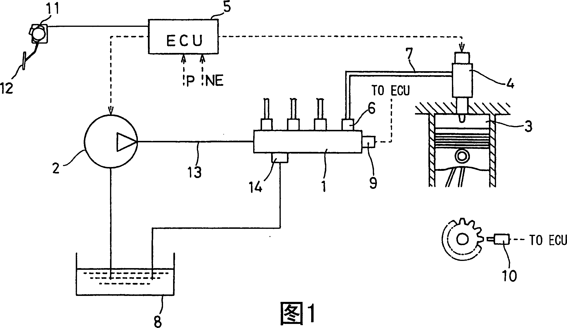
[0070] Referring to FIG. 1, there is shown an accumulator fuel injection system in accordance with a first example embodiment of the present invention.

[0071] For example, the accumulator fuel injection system according to the first embodiment is applied to a four-cylinder diesel engine. As shown in FIG. 1, the fuel injection system has a common rail 1 that stores fuel, a fuel supply pump 2 that pressure-supplies fuel to the common rail 1, and at least one (four cylinders in this embodiment) that inject fuel into a diesel engine. ) injector 4 and so on. An electronic control unit (ECU) 5 controls the fuel injection system.

[0072] The common rail 1 accumulates the fuel supplied by the fuel supply pump 2 up to the injection pressure (target rail pressure). The ECU 5 calculates the target rail pressure in accordance with the operating state of the engine (for example, accelerator position and engine speed). The common rail 1 is formed with the same number of pipe connector...


PUM


Abstract

A ring-shaped connecting portion is formed on a seat surface side of a pipe connector. The connecting portion is tapered so that thickness thereof gradually reduces toward a tip end thereof. A protrusion is formed on the tip end of the connecting portion. A ring-shaped groove is formed on a flat outer peripheral surface of a common rail. By fitting the protrusion into the groove, the connector can be positioned to a predetermined position of the common rail. In this structure, current can be concentrated to the protrusion and current density can be increased. As a result, sufficient bonding strength can be attained.

Description

technical field [0001] The present invention relates to a bonding method and a bonding arrangement for bonding a connection member or a mounting stay for an accumulator fuel injection system to a surface of a metal base material by welding. The present invention also relates to a common rail mounted on a common rail fuel injection system for injecting fuel into an internal combustion engine, the common rail for accumulating high-pressure fuel. In particular, the present invention relates to a bonded common rail formed by welding a plurality of parts. Background technique [0002] When the pipe connector is joined to the common rail of the accumulator fuel injection system of the internal combustion engine, it is required that the joining portion has a certain strength and positioning accuracy. [0003] International Publication No. 01 / 66934 (WO'934) discloses a convex positioning portion on the outer circumferential surface of a common rail. The connector is fitted to the ...

Claims


Application Information

Patent Timeline
Patent Type & Authority Applications(China)
IPC IPC(8): F02M41/00B23K11/00
CPCY02T10/123Y02T10/12
Inventor 山本晃嘉近江义典近藤淳上甲敬三
Owner DENSO CORP
Why Eureka
Try Eureka