
Optical memory

A storage device and optical technology, applied in information storage, recording information storage, recording/reproducing by optical methods, etc., can solve the problem of small capacity of optical storage devices, and achieve the effect of large storage capacity

Inactive Publication Date: 2006-03-15
HONG FU JIN PRECISION IND (SHENZHEN) CO LTD +1
View PDF1 Cites 1 Cited by
  • Summary
  • Abstract
  • Description
  • Claims
  • Application Information

AI Technical Summary

Problems solved by technology

[0007] In order to overcome the defects of the smaller capacity of optical storage devices in the prior art, the present invention provides an optical storage device with larger storage capacity

Method used


Image

  • Optical memory
  • Optical memory
  • Optical memory

Examples


Embodiment Construction

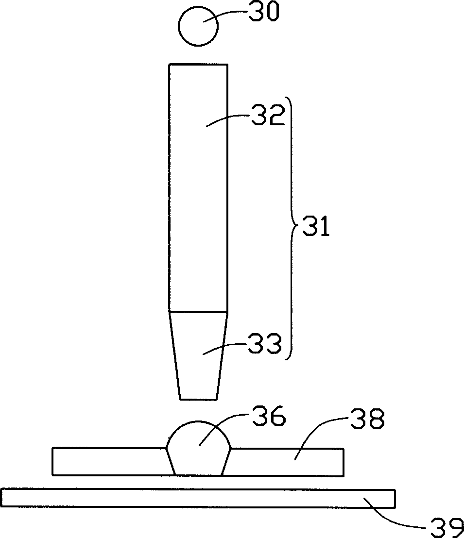
[0014] see figure 2 , is a schematic diagram of the combined use of the optical storage device and the optical storage medium of the present invention. The optical storage device of the present invention includes a light source 30 , an optical fiber 31 and a solid immersion lens 36 supported by a slider 38 . An optical storage medium 39 is used in conjunction with the device. The optical fiber 30 includes a transmission part 32 with an input end (not shown) facing the light source 30 and a sharp part 33 with an output end (not shown) facing the solid immersion lens 36 . The sharp portion 33 can be formed by melting or chemically eroding the optical fiber, and the slider 38 can float the solid immersion lens 36 in the same way as the slider 28 in the prior art.

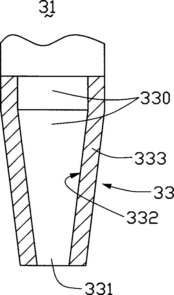
[0015] see image 3 ,yes figure 2 The cross-sectional enlarged schematic view of the sharp portion 33 of the optical fiber 31 shown in . The optical fiber 31 has an inner core 330 and an outer cladding 333. The ...


PUM

PropertyMeasurementUnit
diameteraaaaaaaaaa
thicknessaaaaaaaaaa

Abstract

An optical storage unit consists of a light emitting and receiving device and a light-transmitting device. It features that light transmitting device has an input end and an output end, light emitting and receiving device set at input end of light transmitting device as its output end set with a microhole in diameter of 5 ¿C 70 nanometer.

Description

【Technical field】 [0001] The invention relates to an optical storage device, in particular to a near-field optical storage device. 【Background technique】 [0002] Optical discs are commonly used storage devices and are widely used due to their large capacity and easy portability. The capacity of ordinary VCD discs is mostly 640MB, while the capacity of DVD discs can reach 5GB. As audio-visual works are gradually recorded in the form of digital image data and the large-scale development of software, the requirements for the storage capacity of optical discs are also higher. [0003] The storage capacity of an optical disc depends on the recording density. The smaller the recording spot size, the higher the recording density and the greater the capacity of the optical disc. However, in the far-field conditions, further recording of the point size will be due to the diffraction limitation of light, that is, r≥0.66λ / NA, where r is the size of the recording point, λ is the wave...

Claims


Application Information

Patent Timeline
Patent Type & Authority Applications(China)
IPC IPC(8): G11B7/00G11B11/24
Inventor 陈杰良
Owner HONG FU JIN PRECISION IND (SHENZHEN) CO LTD
Learn More