Radiator and its production thereof

A technology of heat dissipation device and manufacturing method, which is applied in the direction of cooling/ventilation/heating transformation, instrument cooling, instrument, etc., which can solve the problems of increasing the overall weight, easy deformation, and weakening heat dissipation rate of the thermal uniform temperature cavity.

Inactive Publication Date: 2006-03-15
DELTA ELECTRONICS INC
View PDF0 Cites 10 Cited by
  • Summary
  • Abstract
  • Description
  • Claims
  • Application Information

AI Technical Summary

Problems solved by technology

However, due to the phenomenon of metal annealing after high-temperature sintering, the metal cavity will soften. In order to avoid the softening of the metal cavity, it is easy to deform once it is subjected

Method used


Image

  • Radiator and its production thereof
  • Radiator and its production thereof
  • Radiator and its production thereof

Examples


Embodiment Construction

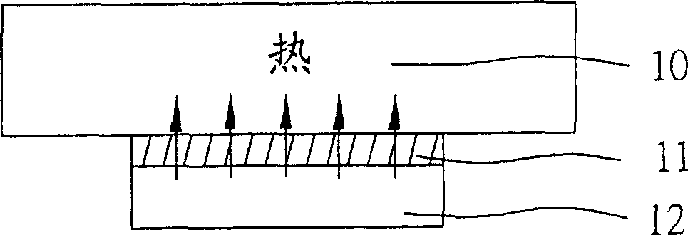
[0031] Please refer to figure 1 , which shows a schematic diagram of a heat dissipation device in a preferred embodiment of the present invention and the heat-generating components applied thereto. The heat dissipating device 10 of the present invention is a heat uniform chamber (vapor chamber), which is applied to a heat generating component 12, such as a CPU. exist figure 1 Among them, a metal bottom plate 11, such as a copper bottom plate, can be directly attached to the top of the heating component 12, and the heat sink 10 is arranged on the bottom plate 11, so the heat generated by the heating component 12 can be directly conducted through the bottom plate 11. to the heat uniform temperature chamber 10, and quickly transfer heat to the outside through the heat uniform temperature chamber 10.

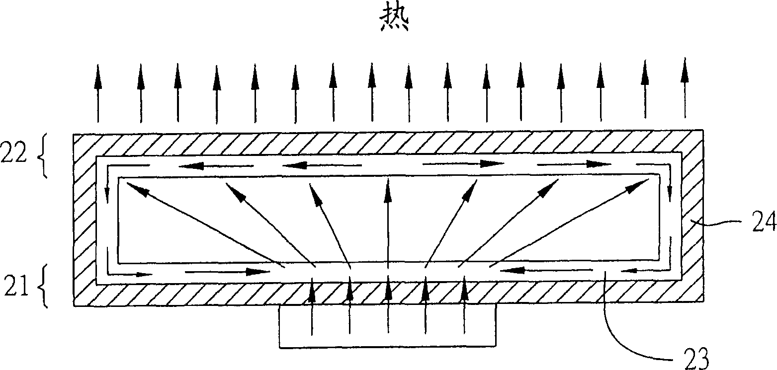
[0032] Please refer to figure 2 , which shows a cross-sectional view of the thermal uniform chamber. The heat equalization cavity 10 includes a cavity, a working fluid, an evap...


PUM


Abstract

A heat dissipation device for a heat-generating package is composed of a cavity, a working fluid, an evaporating unit, a condensing unit, and fine grooves. Its preparing process includes such steps as preparing die, and using the die to prepare said evaporating unit, condensing unit and fine grooves on the inner surface of said cavity.

Description

technical field [0001] The invention relates to a heat dissipation device and a manufacturing method thereof, in particular to a heat uniform temperature chamber and a manufacturing method thereof. Background technique [0002] With the advancement of technology, the number of transistors per unit area of ​​electronic components is increasing, resulting in an increase in heat generation during operation. Therefore, in order to maintain the electronic components at an effective operating temperature, most of the current methods use external fans and cooling fins to deal with the heat dissipation. And because the heat pipe (heatpipe) can transmit a large amount of heat for a considerable distance under a small cross-sectional area and temperature difference, and can work without an external power supply, it does not require power supply and space utilization economy In consideration, heat pipes are already one of the widely used heat transfer components in electronic cooling ...

Claims


Application Information

Patent Timeline
IPC IPC(8): H05K7/20G12B15/06G12B15/02
Inventor 陈彦羲林祺逢陈锦明蔡欣昌王宏洲
Owner DELTA ELECTRONICS INC
Why Eureka
Try Eureka