Portable parabolin antenna

A parabolic antenna, portable technology, applied in the direction of antenna, antenna support/mounting device, electrical components, etc., can solve the problem of inaccessibility, achieve the effect of shortened assembly and disassembly time, increased rigidity, and improved surface shape accuracy

Inactive Publication Date: 2006-03-29
NAT ASTRONOMICAL OBSERVATORIES CHINESE ACAD OF SCI
View PDF0 Cites 22 Cited by
  • Summary
  • Abstract
  • Description
  • Claims
  • Application Information

AI Technical Summary

Problems solved by technology

The supporting structures of the existing parabolic antenna bases cannot meet the above requirements

Method used


Image

  • Portable parabolin antenna
  • Portable parabolin antenna
  • Portable parabolin antenna

Examples


Embodiment Construction

[0023] The antenna structure of the present invention is suitable for antennas with an antenna caliber less than 3 meters. After the parts are disassembled, they can be sorted and packed in knapsacks, and can be carried to the work site manually. Only simple hand tools can be used to quickly install and adjust them on site. , into the working state, is a portable antenna.

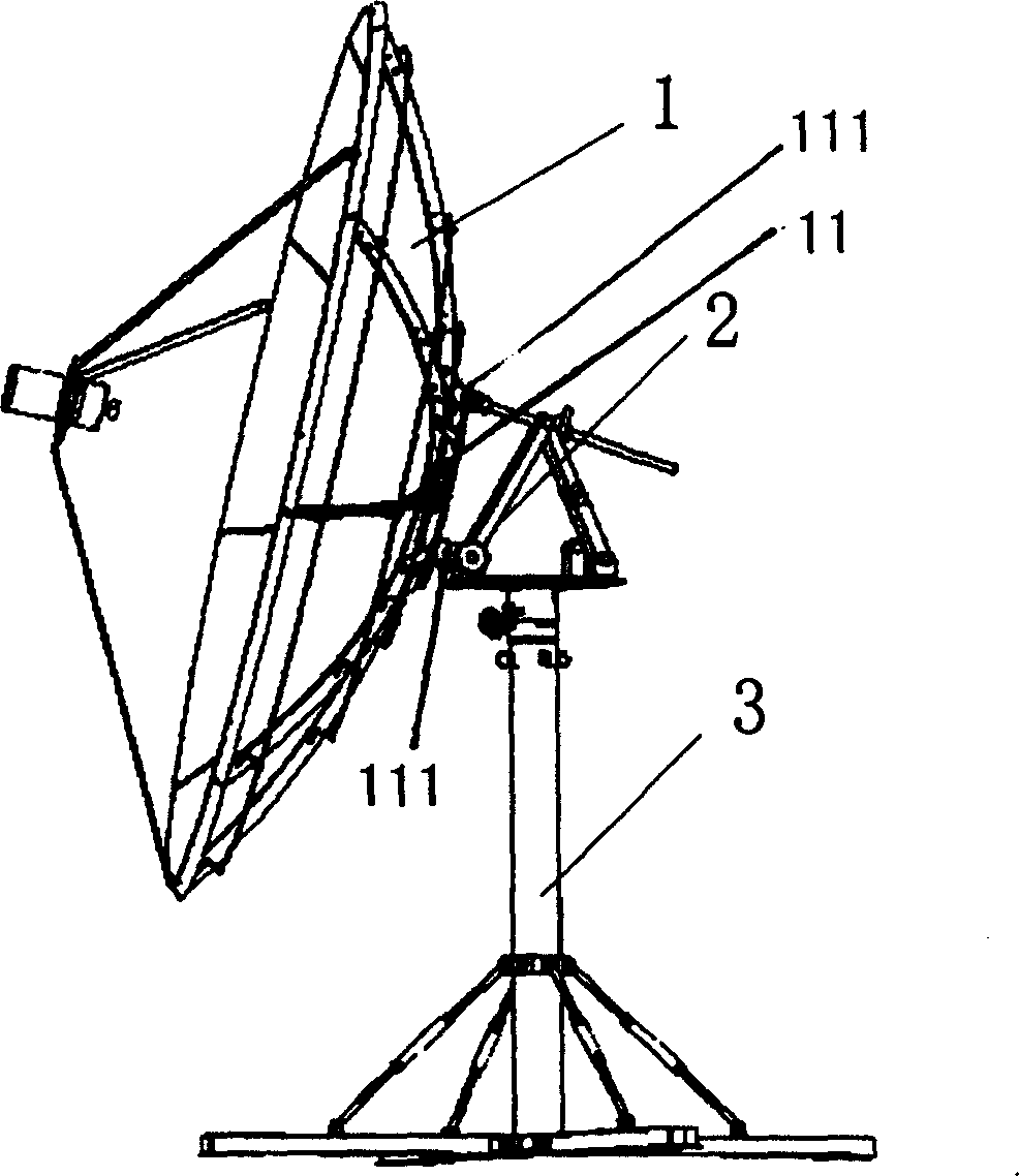
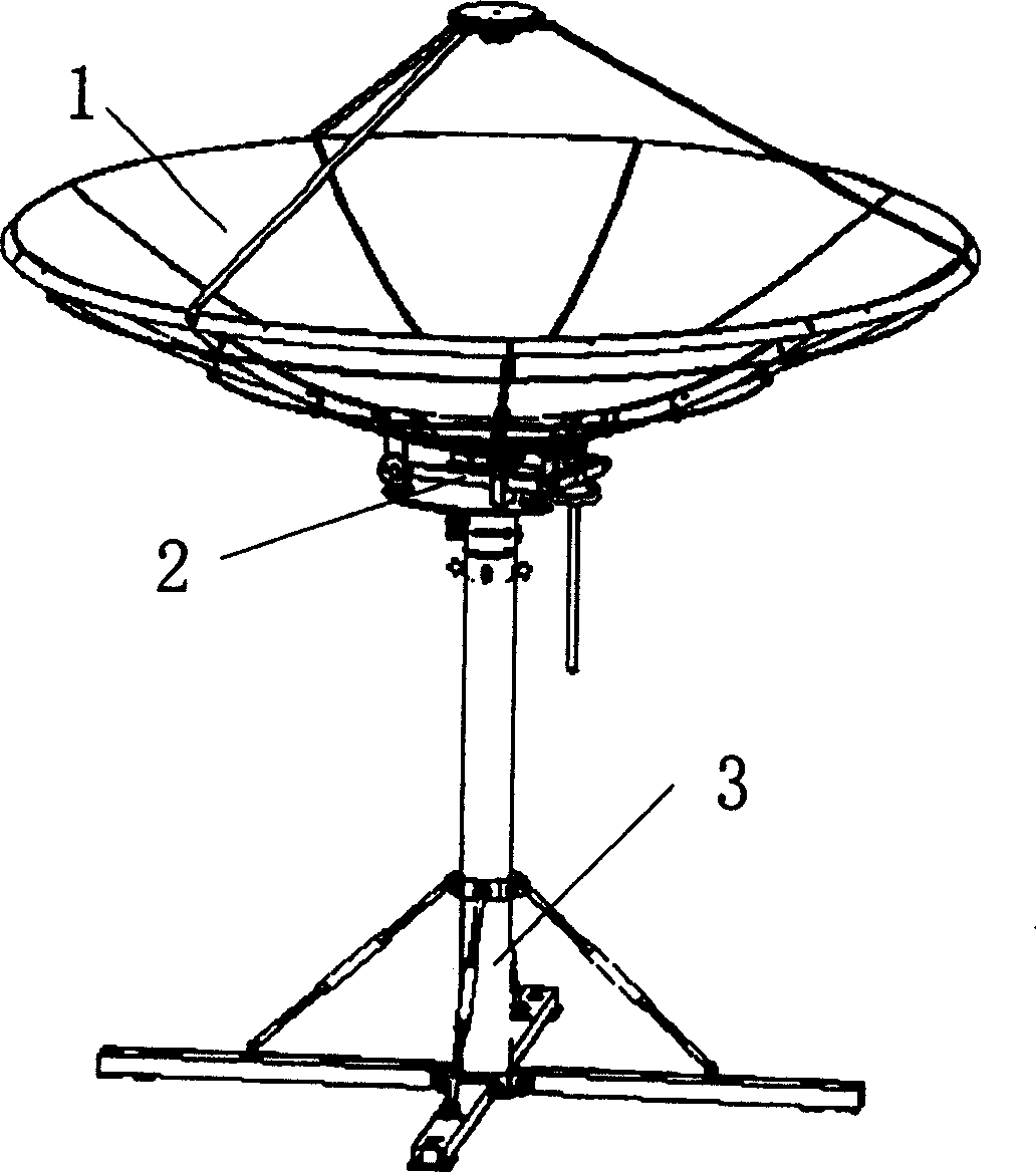
[0024] See Figure 1(A) and Figure 1(B). The parabolic antenna structure is generally composed of a parabolic reflector 1 and an antenna mount. The antenna mount is mostly an azimuth / pitch mount, which consists of an azimuth / pitch adjustment structure 2 and a mount support structure 3 . The top of the back side of the parabolic reflector 1 is fixedly connected with a fixed seat 11, and there are three supporting legs 111 at appropriate positions on it. The three legs 111 of the parabolic reflector 1 are dynamically connected to one side of the azimuth / pitch adjustment structure 2 in a rotatable manner. The...


PUM


Abstract

The invention relates to a portable paraboloid antenna, comprising a paraboloid reflector spliced rapidly of soft steel ropes, an azimuth / pitching angle adjustment mechanism having arm spindle, able to be rapidly drawn or spread and making screwed finite adjustment, and a crossed adjustable seat frame supporting structure, where the top of the back of the paraboloid reflector is fixed with a fixed seat, there are three stand bars in the proper positions on the seat, the three stand bars are rotatably connected on one side of the azimuth / pitching angle adjustment mechanism; the azimuth / pitching angle adjustment mechanism is fixed on the top end of the seat frame supporting structure; the seat frame supporting structure stands on the ground or corresponding platform. The invention has the characters of simple structure, light weight, good maneuverability, etc, suitable to be used by small group taking part in the field work or on occasion of needing to often move.

Description

technical field [0001] The invention relates to the technical field of radio equipment, in particular to a portable parabolic antenna for radiating and receiving electromagnetic waves, which is widely used in the fields of broadcasting, communication, astronomy, meteorology, navigation, aviation, aerospace, national defense and the like. Background technique [0002] There are many types and types of antennas. According to different uses and mobility requirements, the antenna structure is divided into two types: fixed and mobile. Compared with fixed antennas, mobile antenna equipment is not always fixed at a certain place when in use, but needs to be fixed. Antennas that are often moved and dismantled, easy to carry and erect. [0003] With the development of science and technology, there is a need for portable antennas suitable for field work teams and combat teams. This type of antenna belongs to the mobile antenna, but for the more traditional mobile antenna, there are ...

Claims


Application Information

Patent Timeline
Patent Type & Authority Applications(China)
IPC IPC(8): H01Q3/08H01Q1/12H01Q15/16
Inventor 施浒立吕兴荣张巨勇陈志平朱剑鹤
Owner NAT ASTRONOMICAL OBSERVATORIES CHINESE ACAD OF SCI
Why Eureka
Try Eureka