Hydrogen gas storage alloy reactor

A reactor and reaction vessel technology, applied in gas/liquid distribution and storage, non-metallic elements, metal hydrides, etc., can solve the problems of slow hydrogen discharge, slow reaction speed, insufficient reaction, etc. The effect of verticality, improving reactivity, and saving production unit price

Inactive Publication Date: 2006-04-05
LG ELECTRONICS (TIANJIN) APPLIANCES CO LTD
View PDF0 Cites 2 Cited by
  • Summary
  • Abstract
  • Description
  • Claims
  • Application Information

AI Technical Summary

Problems solved by technology

[0018] However, since the hydrogen gas is supplied to the reactor 20, the hydrogen gas can only be supplied to the hydrogen gas storage alloy through the hydrogen gas introduction pipe 22, so the reaction speed between the hydrogen gas storage alloy and the hydrogen gas is slow, and the reaction cannot be sufficiently performed.
[0019] Moreover, when the hydrogen gas in the reactor 20 is released to the outside, when the hydrogen gas in the hydrogen storage alloy 23 is discharged, the hydrogen gas discharge speed is slow because the hydrogen gas can only be discharged through the hydrogen gas introduction pipe 22.

Method used


Image

  • Hydrogen gas storage alloy reactor
  • Hydrogen gas storage alloy reactor
  • Hydrogen gas storage alloy reactor

Examples


Embodiment Construction

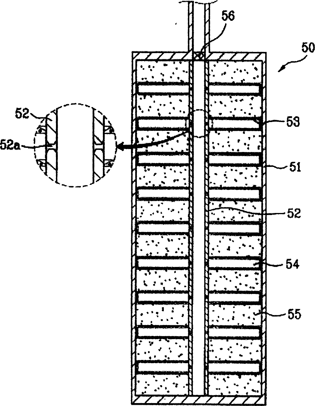
[0043] The first example of the hydrogen storage alloy reactor in the present invention is illustrated below, with reference to the attached image 3 And accompanying drawing 5 to illustrate.

[0044] image 3 A longitudinal sectional view showing a first example of a hydrogen storage alloy reactor in the present invention, Figure 4a hint image 3 The oblique view of the network pore structure, Figure 4b prompt will Figure 4a The cross-sectional view of the mesh holes cut in the shortest direction.

[0045] Refer to attached image 3 It can be seen that the reactor 50 is composed of a reaction vessel 51 , a hydrogen gas introduction pipe 52 , a mesh hole 53 , and a hydrogen storage alloy 55 .

[0046] The hydrogen gas introduction pipe 52 is inserted into the inside of the reaction vessel 51, and a plurality of hydrogen gas inflow grooves 52a are formed to connect the inside and the outside of the hydrogen gas introduction pipe.

[0047] The hydrogen gas introduction...


PUM


Abstract

This invention relates to one heat exchanger by use of hydrogen memory alloy, which in detail to set Hydrogen conductive tube in the reactor to form space between hydrogen memory alloys to improve the reaction between the hydrogen gas memory alloy and hydrogen gas. The invention comprises the following parts: hydrogen conductive tube with several hydrogen flow tank in the reaction container; network holes between hydrogen gas between the hydrogen gas memory alloy. The invention improves the reaction between memory alloy and hydrogen to discharge more hydrogen gas to improve the reaction.

Description

technical field [0001] The present invention is an invention of a reactor utilizing a hydrogen storage alloy. More specifically, a hydrogen gas introduction pipe is provided in the reaction container to form a space between the hydrogen storage alloy blocks to promote the reaction of the hydrogen storage alloy and hydrogen. Background technique [0002] Hydrogen can generally be stored in a liquid state in a high-pressure container under high pressure or ultra-low temperature. [0003] That is, as mentioned above, due to the inherent low density of hydrogen, the amount of hydrogen that can be stored in a high-pressure container under high pressure or ultra-low temperature is limited. Moreover, because the hydrogen storage container is not only bulky and heavy, the use of the transport aircraft is subject to many restrictions. [0004] Recently, as a countermeasure to the hydrogen storage method, a method of absorbing and storing hydrogen using a hydrogen storage alloy has ...

Claims


Application Information

Patent Timeline
Patent Type & Authority Applications(China)
IPC IPC(8): B01J8/02C01B6/00F17C11/00
CPCY02E60/321Y02E60/32
Inventor 金智元姜成姬盛时京具子形朴尚勋金英秀金京浩朴一权许京旭洪永浩车江旭洪尚意金仁奎朴丙日
Owner LG ELECTRONICS (TIANJIN) APPLIANCES CO LTD
Why Eureka
Try Eureka