Turbine overspeed limiting device

一种涡轮机、涡轮的技术,应用在安全装置、发动机控制、机械设备等方向,能够解决增加涡轮整体质量、改变空气动力学轮廓等问题,达到容易生产与实现的效果

Active Publication Date: 2006-04-05
SN DETUDE & DE CONSTR DE MOTEURS DAVIATION S N E C M A
View PDF0 Cites 19 Cited by
  • Summary
  • Abstract
  • Description
  • Claims
  • Application Information

AI Technical Summary

Problems solved by technology

[0008] In addition, the known devices generally have the disadvantage of increasing the overall mass of the turbine and changing the aerodynamic profile of its components

Method used


Image

  • Turbine overspeed limiting device
  • Turbine overspeed limiting device
  • Turbine overspeed limiting device

Examples


Embodiment Construction

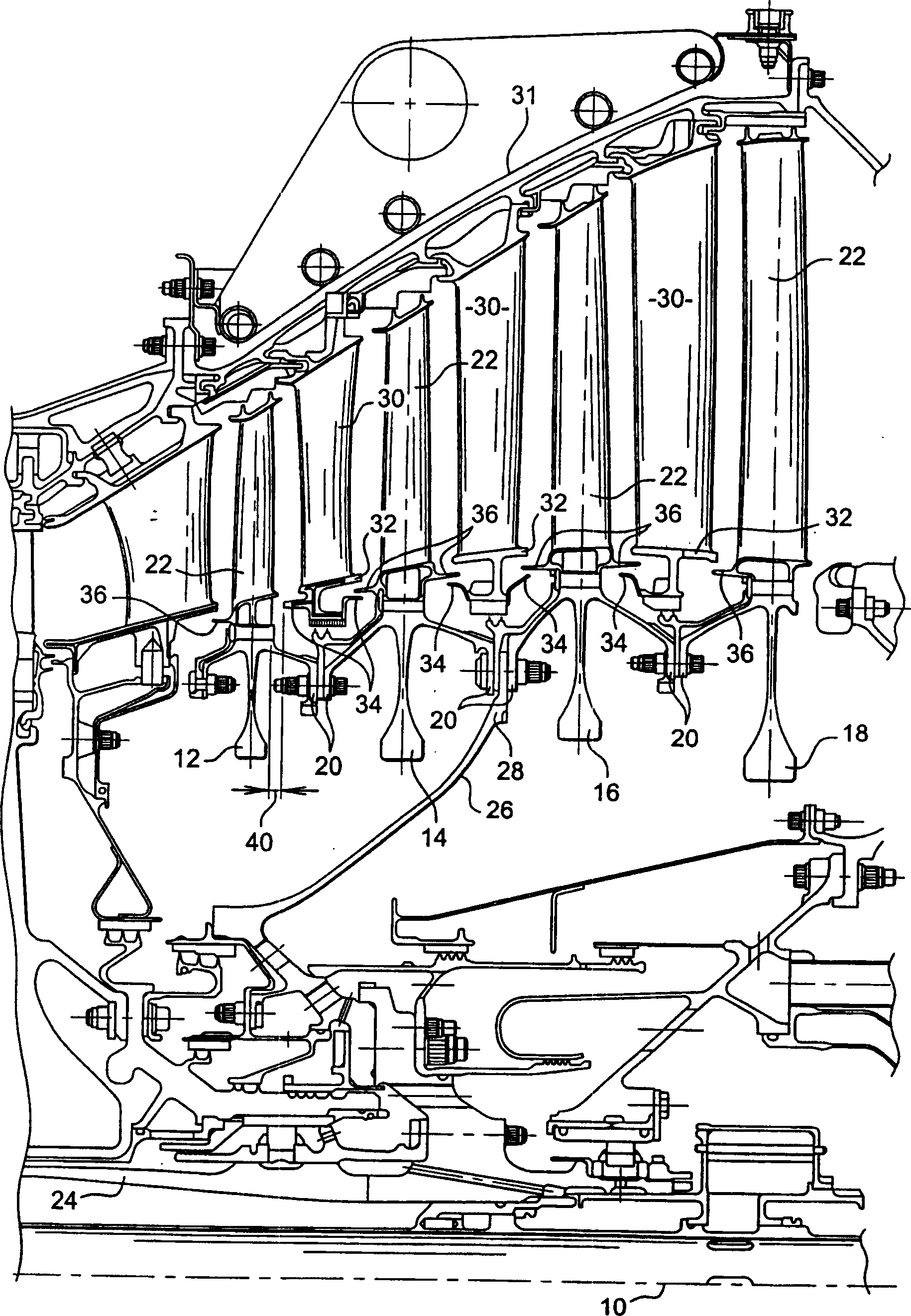
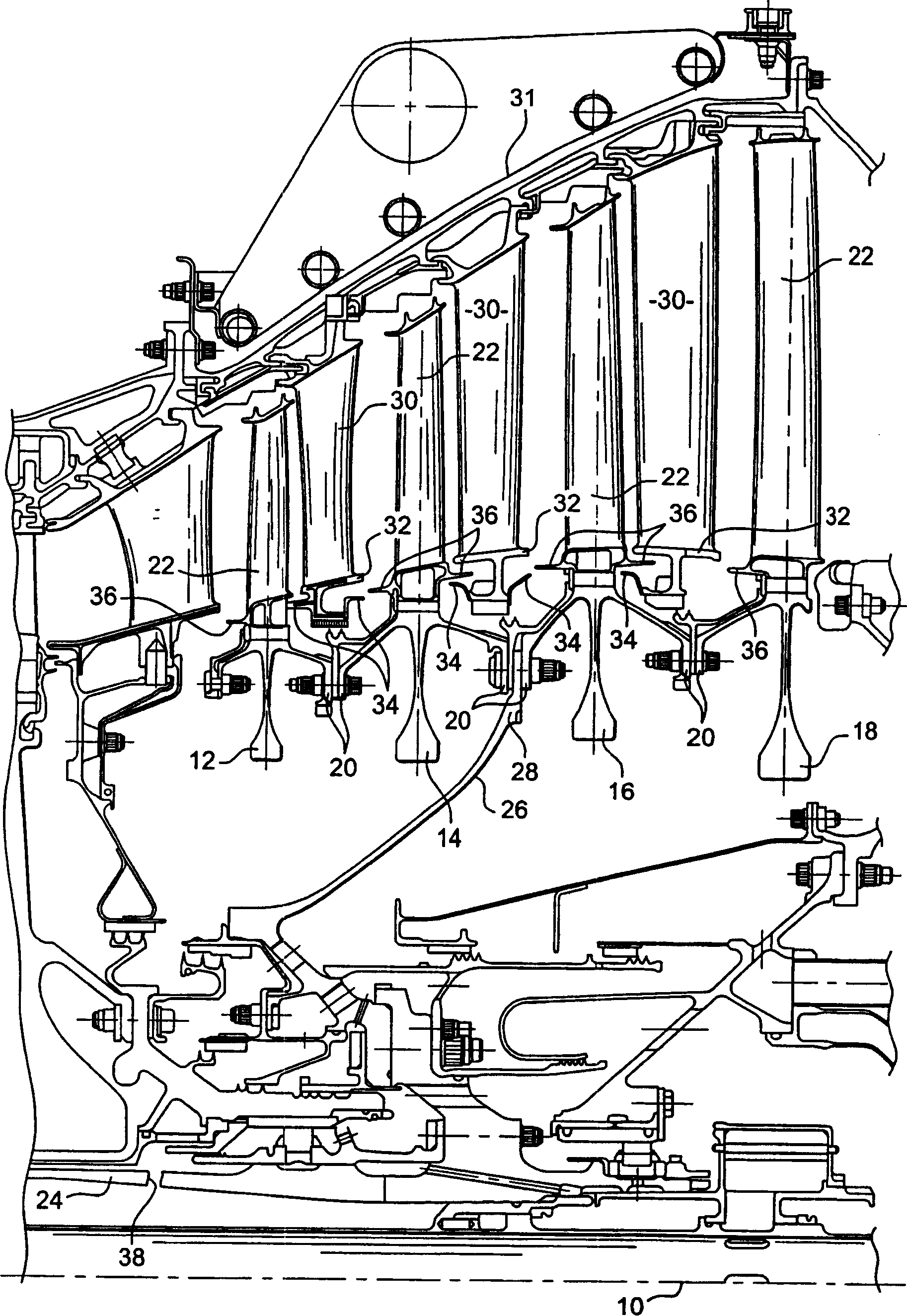
[0031] first reference figure 1 , figure 1 is a schematic half view of a low-pressure turbine of a turbojet engine along a plane passing through the axis of rotation 10 of the rotor of the turbine.

[0032] The rotor of the low-pressure turbine comprises four discs: 12, 14, 16, 18, which are fitted together relative to each other by means of annular flanges 20 and which carry individual blades 22, for example by wedge joints or the like, which pass through the The roots are mounted on the outer boundaries of the discs 12 , 14 , 16 , 18 at their radially inner ends. The rotor is connected to the turbine shaft 24 via an intermediate drive cone 26 which is secured by an annular flange 28 between the annular flanges 20 of the discs 14 and 16 of the rotor of the low pressure turbine.

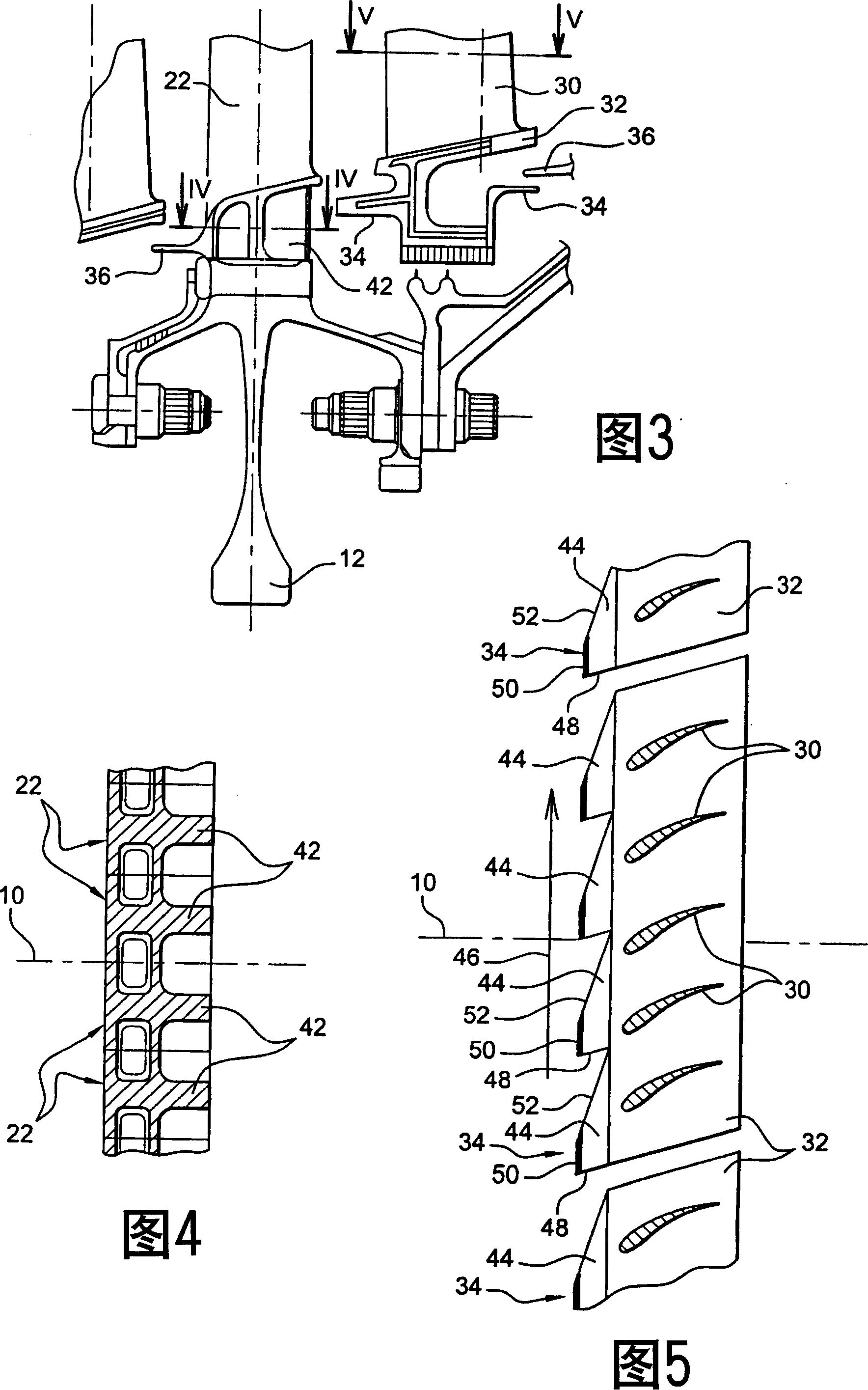
[0033] Between the stages of the rotating blades 22 there are stages of stationary blades 30 which are mounted at their radially outer ends to the casing 31 of the low pressure turbine by suitable ...


PUM


Abstract

The device is formed by an upstream edge (34) of an upstream stage of stator blades (30). The edge forms a shearing unit to shear poles of rotor blades (22), during rupture of a turbine shaft (24). The shearing unit cuts a sufficient part of the poles so that constrain in remaining part is equal or higher than their resistance to the rupture of the blades (22), in order to assure the rupture of the blades (22).

Description

technical field [0001] The present invention relates to a device for limiting turbine overspeed in the event of a fracture of the turbine shaft in a turbomachine, for example in a turbojet engine, Background technique [0002] Fractures of the turbine shaft of a turbine are fortunately rare in practice, such accidents can be caused by poor assembly or lack of protection of the shaft against oxidation. [0003] When the shaft connecting the rotor of the turbine to the fan of the turbine breaks, the rotating blades of the turbine are still driven in rotation by the gases exhausted from the combustion chamber of the turbine, but have disengaged from the fan which limits their speed of rotation. The turbine then idles and enters an "overspeed" condition which places the rotating blades under excessive stress which can cause the rotor to explode, with the potential to penetrate both the casing of the turbine and the fuselage of the aircraft on which the turbine is fitted. risk. ...

Claims


Application Information

Patent Timeline
Patent Type & Authority Applications(China)
IPC IPC(8): F01D9/02F01D21/00
CPCF05B2270/1011Y02T50/671F05D2270/021F01D21/02F01D21/045Y02T50/60
Inventor 让-吕克·苏皮宗
Owner SN DETUDE & DE CONSTR DE MOTEURS DAVIATION S N E C M A
Why Eureka
Try Eureka