Method and reactor for production of aluminum by carbothermic reduction of alumina

A technology of reactor and aluminum carbide, which is applied in the field of producing aluminum by carbothermal reduction of alumina and the reactor field, which can solve the problems of aluminum yield loss and the like

Inactive Publication Date: 2006-04-05
ARCONIC INC +1
View PDF2 Cites 3 Cited by
  • Summary
  • Abstract
  • Description
  • Claims
  • Application Information

AI Technical Summary

Problems solved by technology

If not recycled, these volatiles will cause a loss of aluminum yield

Method used


Image

  • Method and reactor for production of aluminum by carbothermic reduction of alumina
  • Method and reactor for production of aluminum by carbothermic reduction of alumina
  • Method and reactor for production of aluminum by carbothermic reduction of alumina

Examples


Embodiment Construction

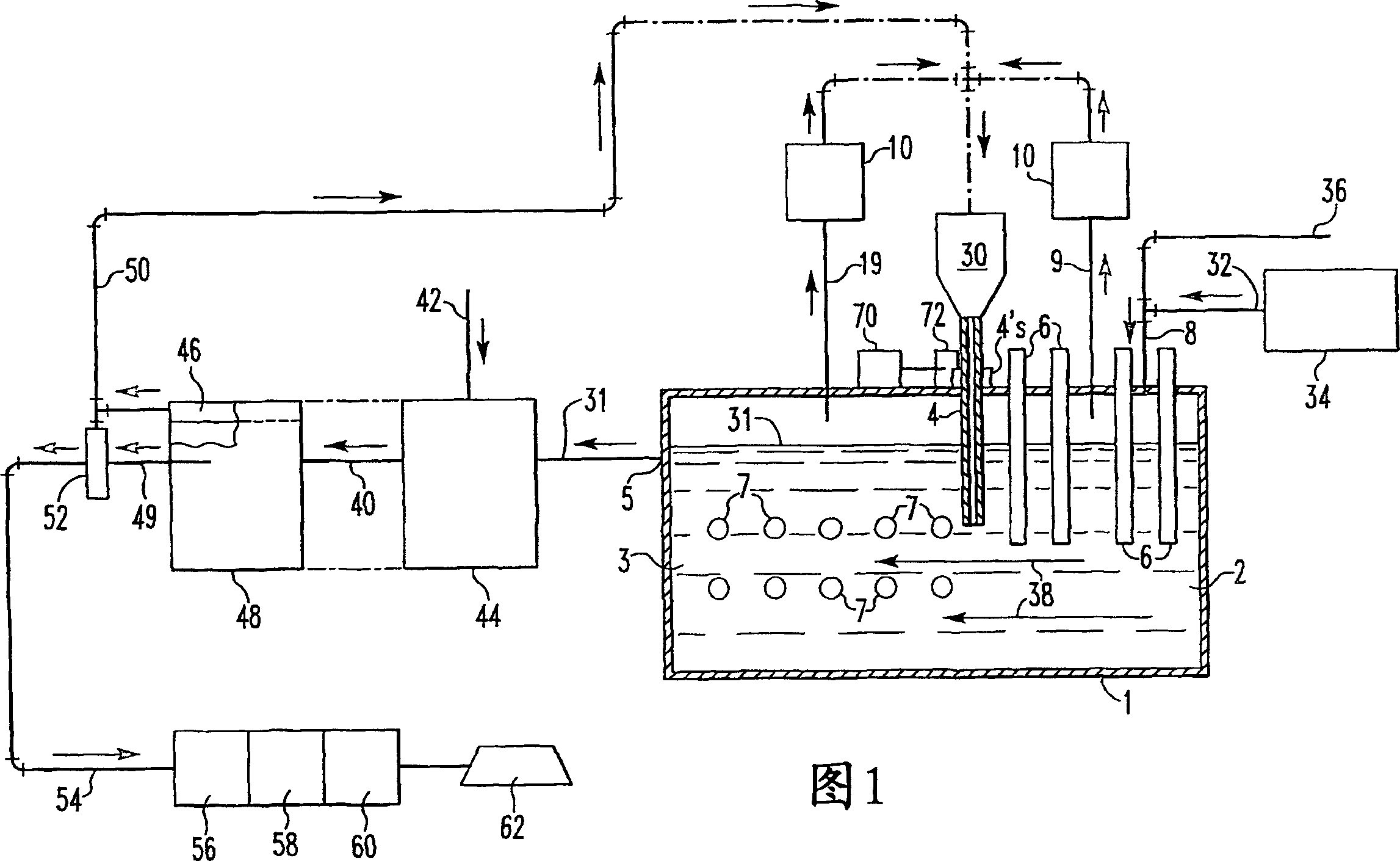
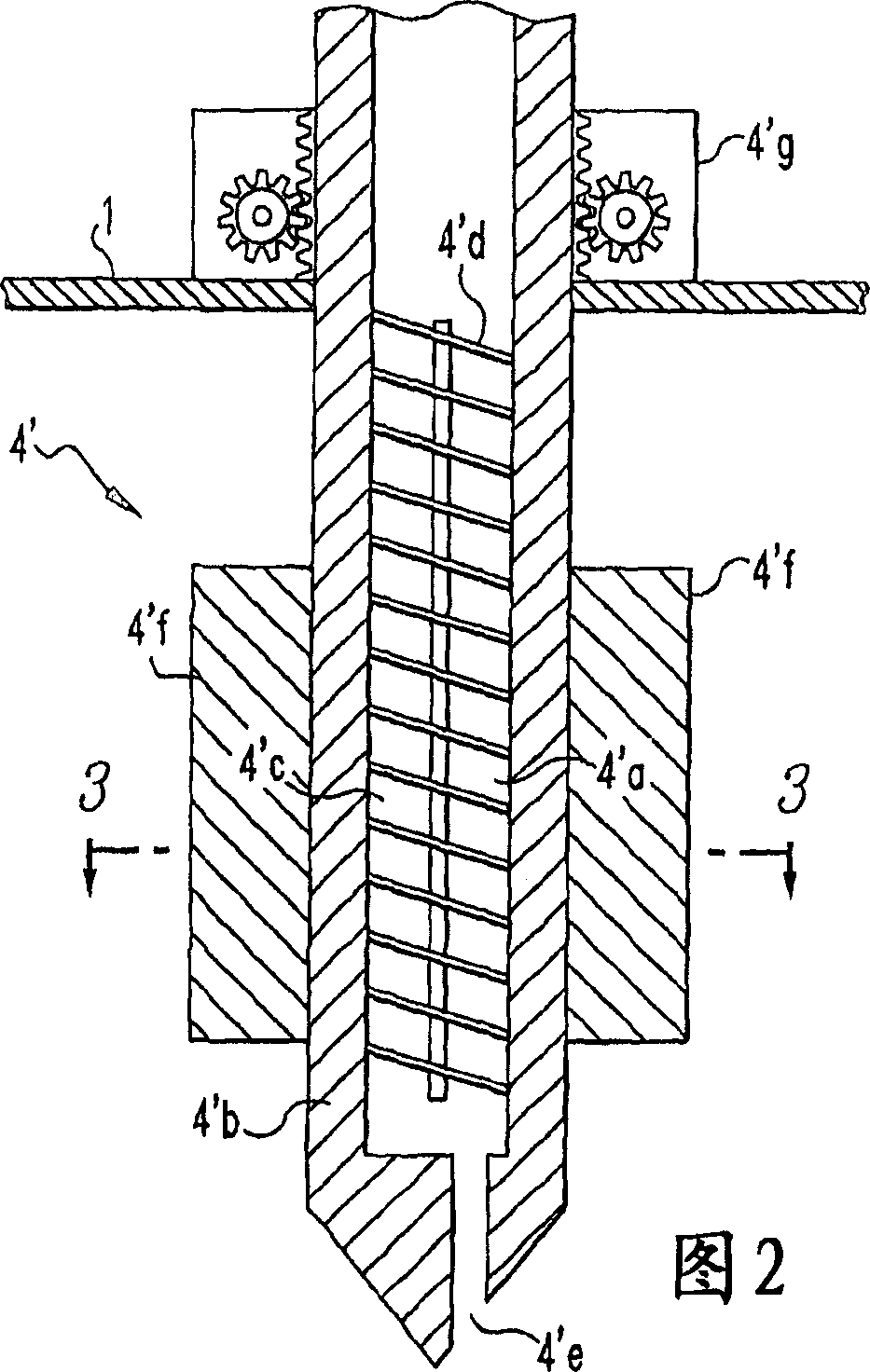
[0020] Figure 1 shows a generally rectangular, airtight reaction vessel 1 divided into a low-temperature compartment 2 and a high-temperature compartment 3 by a hollow underflow partition 4 which allows a molten bath to flow from the low-temperature compartment 2. The flow is to the high temperature compartment 3 and additional carbon material is added to the flow of the molten bath as the molten bath passes below the partition 4 . At one end of the high-temperature compartment 3 opposite to the low-temperature compartment 2 , an outlet 5 is arranged for leading out or taking out the molten aluminum layer 31 . The molten bath flows from the low temperature compartment 2 to the high temperature compartment 3 by gravity. This flow is influenced and regulated by tapping the aluminum 31 at the outlet 5 . When the aluminum is withdrawn from the high temperature compartment, a corresponding amount of molten bath flows from the low temperature compartment into the high temperature c...


PUM


Abstract

A hollow partition wall (4) is employed to feed carbon material to an underflow of a carbothermic reduction furnace used to make aluminum. The partition wall (4) divides a low temperature reaction zone (2) where aluminum oxide is reacted with carbon to form aluminum carbide and a high temperature reaction zone (3) where the aluminum carbide and remaining aluminum oxide are reacted to form aluminum and carbon monoxide.

Description

field of invention [0001] The present invention relates to a process for the production of aluminum by carbothermal reduction of alumina and a reactor for the production of aluminum by carbothermal reduction of alumina. Background technique [0002] The direct carbothermal reduction of alumina is disclosed in US Patent No. 2974032 (Grunert et al.), and it has long been believed that the following overall reaction occurs: <chemistry num="001"> <chem file="200480006134_cml001.xml" / > < / chemistry> (1), or the reaction occurs in two steps: <chemistry num="002"> <chem file="200480006134_cml002.xml" / > < / chemistry> (2); and <chemistry num="003"> <chem file="200480006134_cml003.xml" / > < / chemistry> (3). [0003] Reaction (2) occurs below 2000°C. Reaction (3) is the reaction to produce aluminum, which occurs at slightly higher temperatures of 2200°C and higher; the reaction rate increases with increasing temperature. In ad...

Claims


Application Information

Patent Timeline
Patent Type & Authority Applications(China)
IPC IPC(8): C22B21/02C22B5/06C22B5/10C22B5/18C22B21/06
CPCC22B5/06C22B5/10C22B21/06C22B21/02C22B5/18
Inventor J·A·奥内K·约翰森
Owner ARCONIC INC
Why Eureka
Try Eureka