Rotary electric machine comprising a stator and two rotors

An electric and mechanical technology, applied to synchronous motors with stationary armatures and rotating magnets, motors, electric vehicles, etc., can solve problems such as complex manufacturing of electric machinery, achieve simplified structure, reduce torque ripple, and improve reliability Effect

Inactive Publication Date: 2006-04-05
MOTEURS LEROY SOMER
View PDF4 Cites 13 Cited by
  • Summary
  • Abstract
  • Description
  • Claims
  • Application Information

AI Technical Summary

Problems solved by technology

The manufacture of such electric machinery is more complicated

Method used


Image

  • Rotary electric machine comprising a stator and two rotors
  • Rotary electric machine comprising a stator and two rotors
  • Rotary electric machine comprising a stator and two rotors

Examples


Embodiment Construction

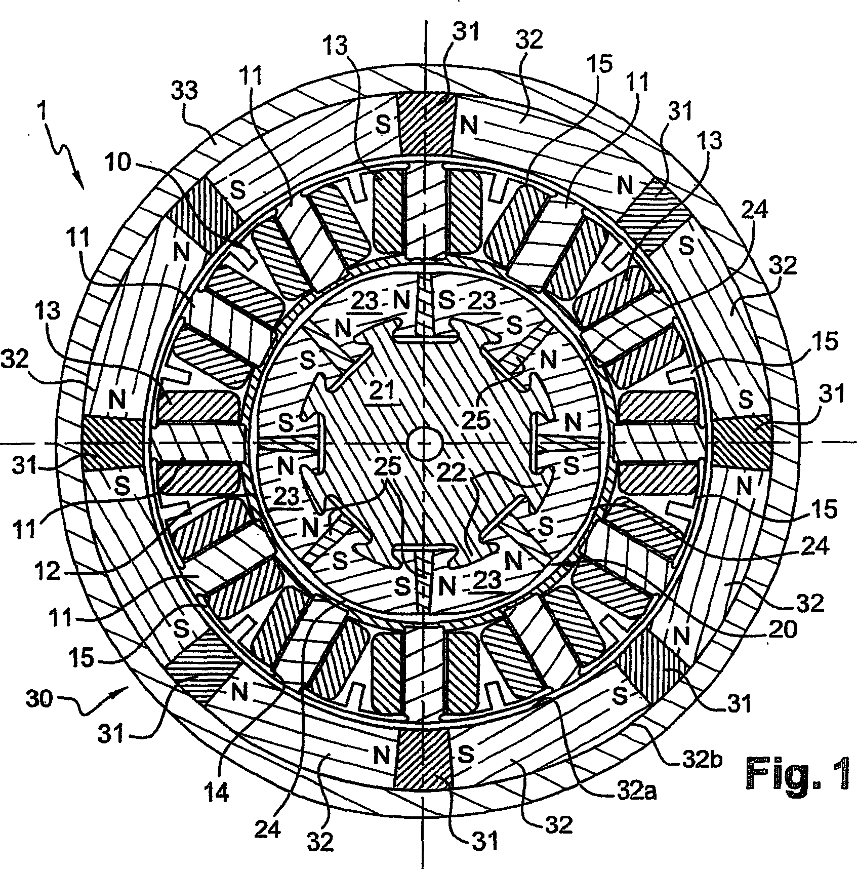
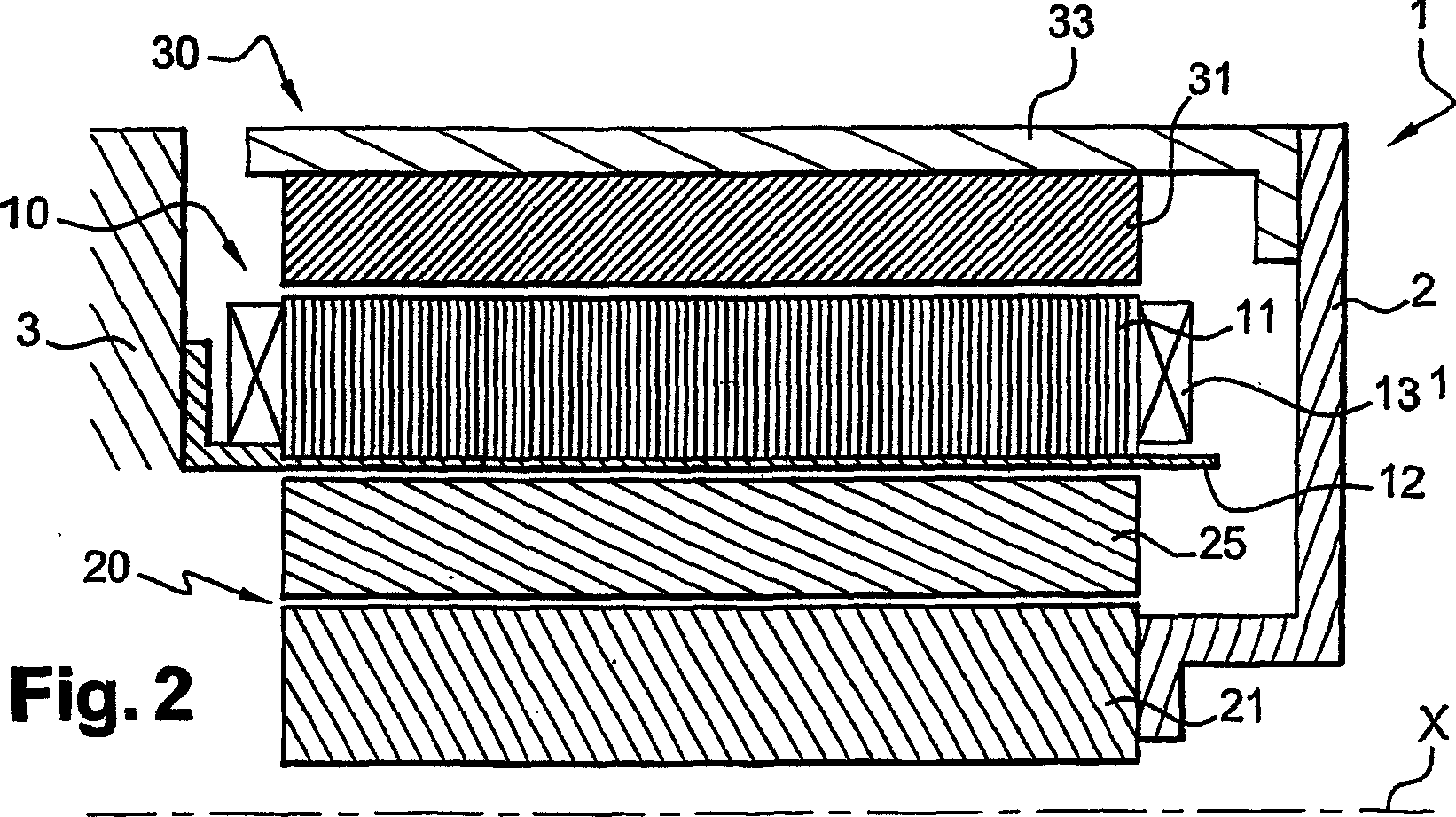
[0044] As shown in FIG. 1 and FIG. 2 , an electric machine 1 includes a stator 10 , an inner rotor 20 and an outer rotor 30 , and the inner rotor and the outer rotor are fixed together by a mechanical connection mechanism between the inner and outer rotors.

[0045] The stator 10 has a plurality of stator teeth 11 formed by a stack of magnetically insulated laminations electrically insulated from each other, these stator teeth are fixed to a support 12 made of non-magnetic material such as non-magnetic steel or made of aluminum or insulating material.

[0046] As shown in FIG. 2 , in the embodiment described, the support 12 is fixed to the frame 3 of the electromechanical machine.

[0047] In the embodiment described, the stator teeth 11 are secured via their radially innermost ends to a support 12 , which is generally tubular. The stator teeth 11 can also be fixed to the support 12 by any other means, for example by welding.

[0048] Each stator tooth 11 carries an individu...


PUM


Abstract

The invention relates to an electric machine comprising a stator (10, 40) provided with a plurality of teeth (11, 41), each tooth supporting at lest one individual coil (13, 46, 47), an external rotor (30) which is radially arranged outside the stator and provided with constant magnets, an internal rotor (20) radially arranged inside the stator, provided with constant magnets and connected to the external rotor (30). At least one of the external (30) and internal (20) rotors is disposed in a flux concentration.

Description

technical field [0001] The present invention relates to an electric machine, and more particularly to an electric machine with a stator, an outer rotor and an inner rotor fixed to the outer rotor. Background technique [0002] An electromechanical machine with two concentric rotors is described in International Application WO 91 / 06147. The stator of this electromechanical machine has stator teeth at its ends with pole shoes. The stator coils have tops on which a heat transfer fluid such as oil is sprayed to carry heat away from the windings. The manufacture of such electric machines is relatively complex. [0003] Furthermore, the electromechanical machine described in International Application WO 91 / 06147 is axially longer, mainly due to the coil tops and the means for cooling the coil tops. Contents of the invention [0004] There is a need for a simple and reliable electromechanical machine that does not require cooling of the coils by spraying heat transfer liquid. ...

Claims


Application Information

Patent Timeline
Patent Type & Authority Applications(China)
IPC IPC(8): H02K21/12H02K16/00H02K1/18H02K1/27H02K16/02
CPCH02K16/02H02K1/18H02K1/278H02K1/2786Y02T10/641Y02T10/64H02K1/2791
Inventor 阿戴夫·阿鲍·阿凯埃里克·考帕特杰魁斯·圣-米歇尔
Owner MOTEURS LEROY SOMER
Why Eureka
Try Eureka