Sewing machine

A sewing machine and thread technology, which is applied to sewing machine components, sewing equipment, sewing machine control devices, etc., can solve the problems such as the inability of the presser foot to rise, become unbalanced, and the inability to lower the position of the presser foot, so as to avoid excessive burden, The effect of preventing dissonance

Inactive Publication Date: 2006-04-12
JUKI CORP
View PDF1 Cites 15 Cited by
  • Summary
  • Abstract
  • Description
  • Claims
  • Application Information

AI Technical Summary

Problems solved by technology

[0005] However, when the rotary cam is used to lift the presser foot to the presser mechanism, if the thickness of the object to be sewn is thick, the presser foot cannot be lowered to a predetermined lowering position. The problem that the cam follower of the mechanism cannot rotate around the rotating cam and prevents the rotation of the rotating cam
At this time, there are disadvantages as follows: As for the presser mechanism, since the rotary cam is further rotated to raise the presser foot, the pre

Method used


Image

  • Sewing machine
  • Sewing machine
  • Sewing machine

Examples


Embodiment Construction

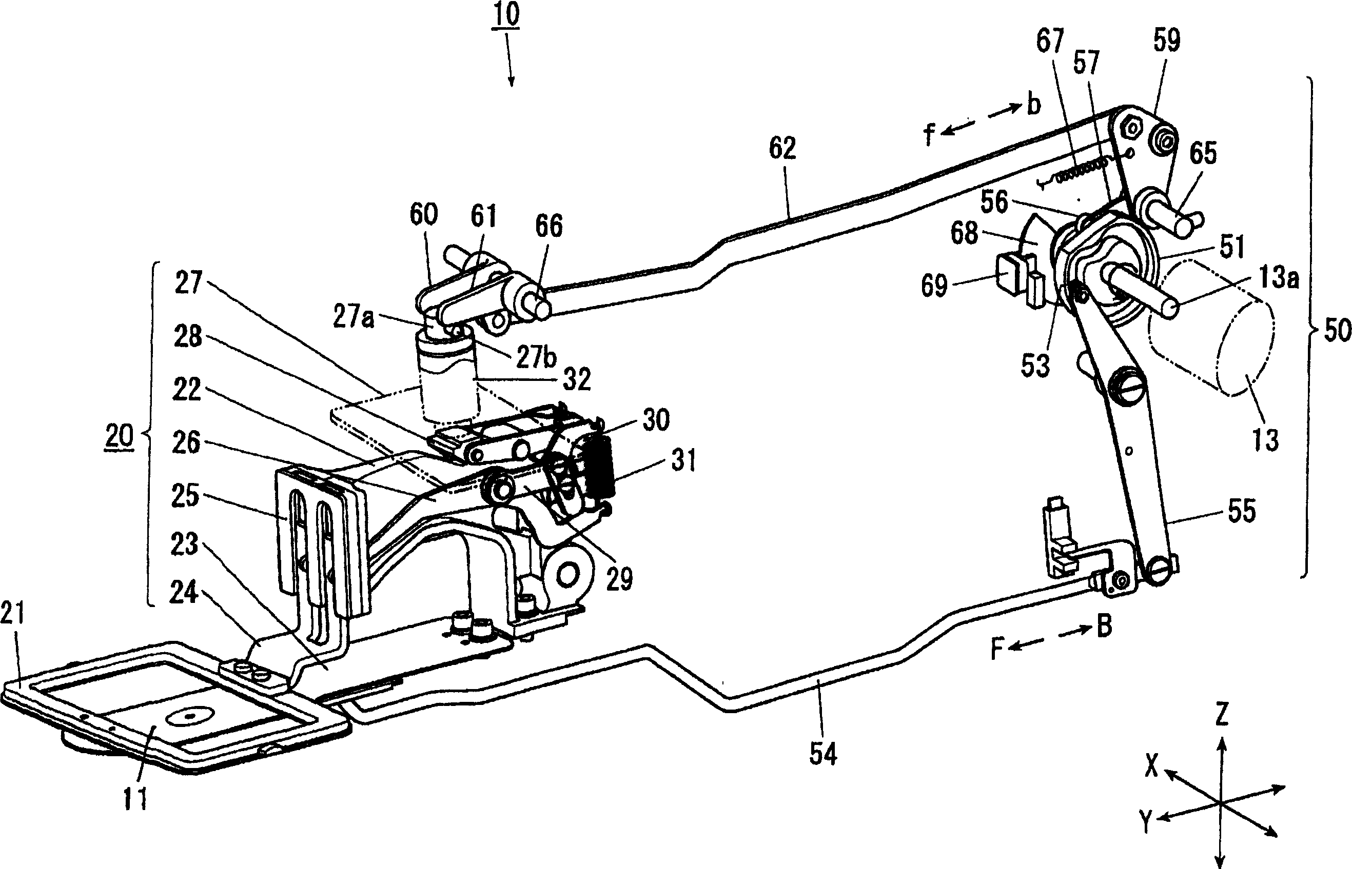
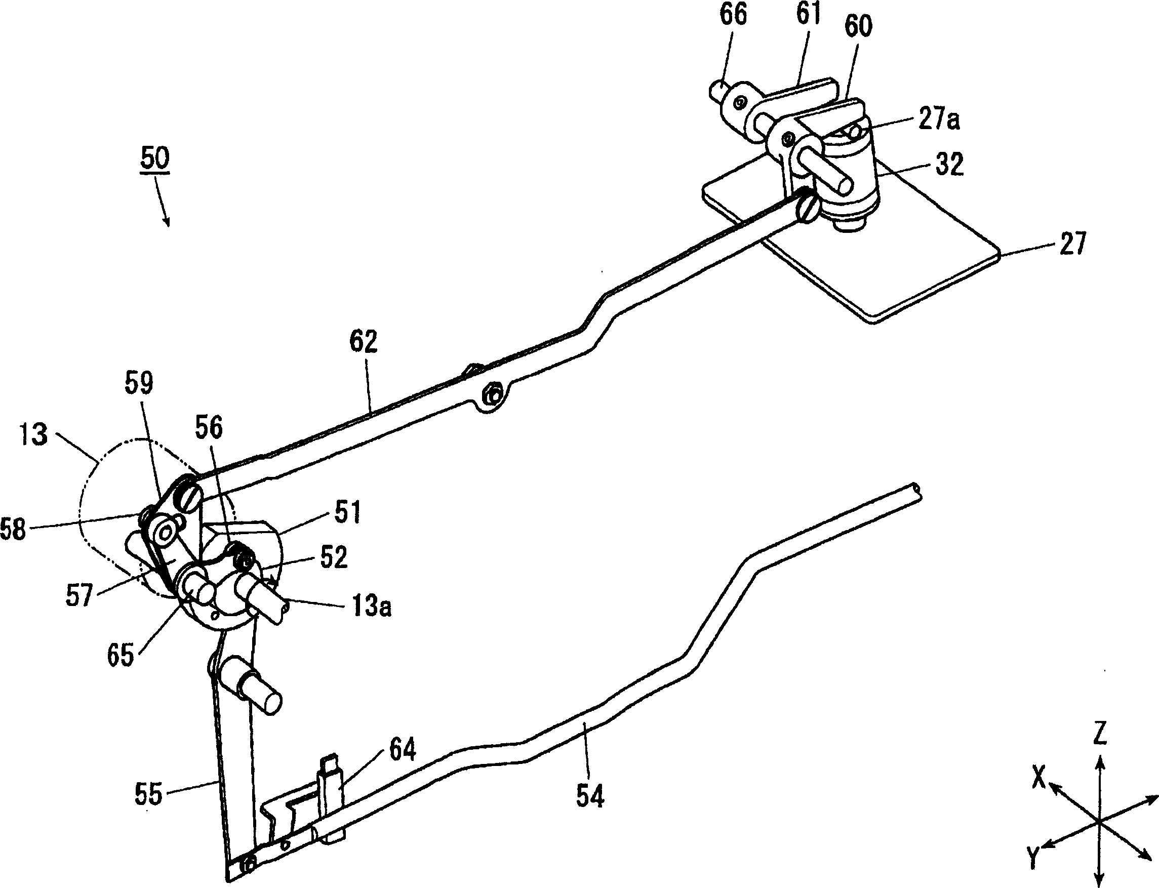
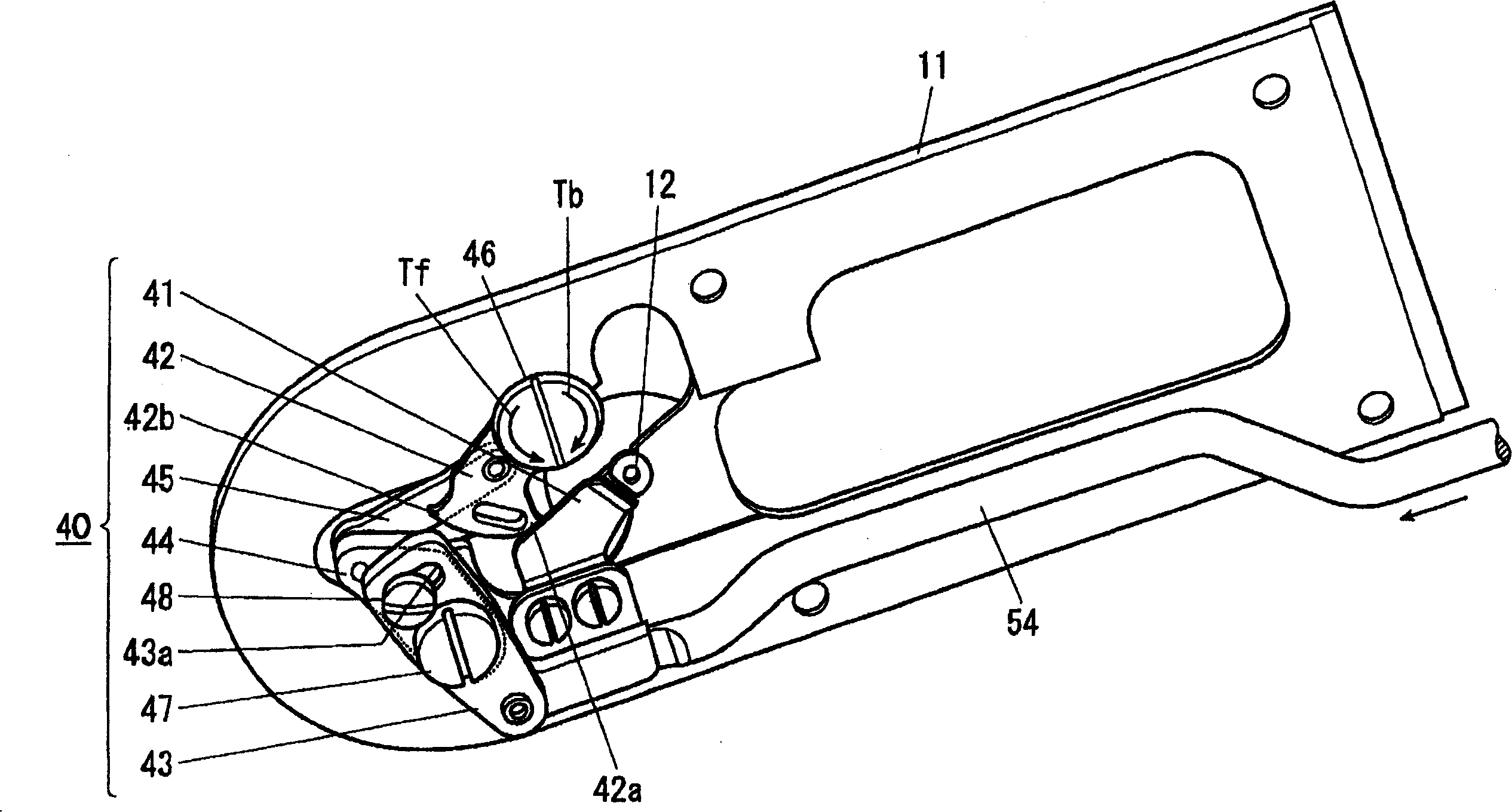
[0021] Below, according to Figure 1 to Figure 6 Examples of the present invention will be described in detail. FIG. 1 is a perspective view showing only the main configuration of a sewing machine 10 as an embodiment of the invention. figure 2 is from and figure 1 A perspective view of only the main components of the sewing machine 10 viewed from different directions.

[0022] The sewing machine 10 includes an unillustrated sewing machine housing for holding or accommodating various components. The vertical fuselage part, the nose part extending in the same direction from the upper end part of the vertical fuselage part and the bottom plate part. In the following description, in the state where the sewing machine 10 is placed on a horizontal plane, the direction parallel to the horizontal and longitudinal direction of the bottom plate portion is referred to as the Y-axis direction, and the direction horizontal and perpendicular to the Y-axis direction is referred to as the...


PUM


Abstract

A seaming machine comprises a cloth press (20) capable of lifting up and down to support a press stand (21), a cutter (40) arranged under a needle plate (11) and provided with a fixed blade (41) and a movable blade (42), a step motor (13) as the drive source of the cloth press (20) and the cutter (40), and a power transmitter (50) for transmitting rotary drive force of the step motor (13) to each mechanism, wherein the power transmitter is provide with two rotary cams (51, 52) driven by the step motor, while the cams can transmit drive force on each mechanism. And an actuating quantity adjuster (59) is arranged between the cloth press and the rotary cams to adjust the driving quantity. The seaming machine can realize optimized rotation of step motor.

Description

technical field [0001] The present invention relates to a sewing machine that continuously operates a cloth press mechanism and other mechanisms connected thereto. Background technique [0002] As is well known, a sewing machine is equipped with a presser mechanism and other mechanisms that press down the presser foot to press the sewing object on the needle plate. single stepper motor. For example, there is a structure in which, for each mechanism, a rotary cam independently imparting a driving force is provided, and each rotary cam is simultaneously rotated by a single stepping motor (for example, refer to Patent Document 1). [0003] On each rotary cam, a transmission mechanism composed of a swinging arm and a plurality of link members is provided separately through the cam follower, and the cloth pressing mechanism and the cutting mechanism follow a predetermined sequence through one rotation of the stepping motor. Take action. [0004] Patent Document 1: JP-A-2003-21...

Claims


Application Information

Patent Timeline
IPC IPC(8): D05B29/02D05B65/02D05B69/12
CPCD05B29/02D05B37/06D05B65/02D05B69/30
Inventor 桥口俊一
Owner JUKI CORP
Why Eureka
Try Eureka