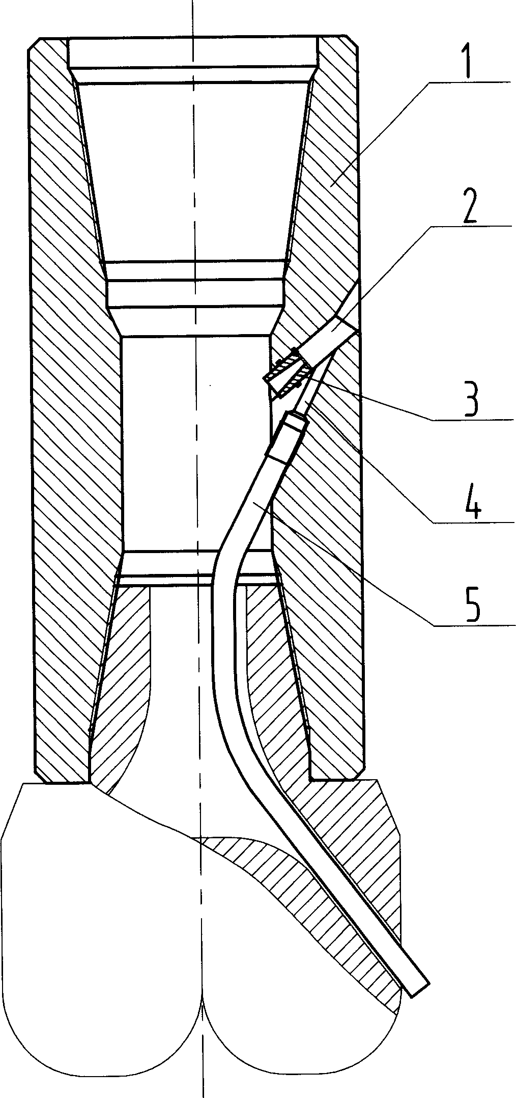
Well bottom hydraulic suction pressure lowering drilling tool

A drilling tool and hydraulic technology, which is applied to drilling equipment, drill bits, earthwork drilling and production, etc., can solve the problems of easy well damage, well hole expansion, large investment, etc.

Inactive Publication Date: 2006-04-12
SHENGLI PETROLEUM ADMINISTRATION BUREAU DRILLING TECH ACAD SINOPEC
View PDF0 Cites 3 Cited by
  • Summary
  • Abstract
  • Description
  • Claims
  • Application Information

AI Technical Summary

Problems solved by technology

However, at this stage, the underbalanced technology of the whole well section is only applicable to some formations, and this technology has high requirements for equipment capacity, large investment, and is prone to complex situations such as well spattering and borehole expansion, and the conditions for large-scale application are not yet mature.

Method used


Image

  • Well bottom hydraulic suction pressure lowering drilling tool

Examples


Embodiment Construction

[0008] The present invention will be further described now in conjunction with the accompanying drawings of the description.

[0009] When the present invention is used to form a local low pressure at the bottom of the well, the drill bit connecting nipple [1] is axially penetrated, the two ends are processed with threads, the upper end and the lower end are respectively connected with the drill string and the drill bit, and in the middle of the drill bit connecting nipple [1] A low-pressure chamber [2] is processed, and the outlet of the low-pressure chamber [2] points to the direction of the annular space. ] installed in the low-pressure chamber [2] close to the inner wall of the drill nipple [1], and an ejection cavity [4] is processed at the exit of the injection nozzle [3] and the middle of the drill nipple [1]. The axis of the chamber [4] intersects the axis of the low-pressure chamber [2]. In the ejection chamber [4], one end close to the inner wall of the drill joint p...


PUM


Abstract

A well drilling tool able to decrease the pressure at well bottom by hydraulic sucking for increasing the drilling efficiency is composed of drill bit and its short joint segment, low-pressure cavity, jet nozzle, jet cavity and sucking tube. A high-speed jet from said nozzle is generated by the difference between the pressures in drilling column and annular space to form a local low pressure near the nozzle outlet. A sucking tube is used to deliver the low pressure to well bottom.

Description

technical field [0001] The invention belongs to a supporting device for oil and natural gas drilling. technical background [0002] Under the effect of the bottom hole fluid column pressure and formation pore fluid pressure difference, the cuttings generated by the drill bit breaking the rock are pressed in place and repeatedly cut by the drill bit, which hinders the exposure of the new broken surface of the rock and improves the drilling efficiency of the bit. This is the so-called "holding effect", so whether the "holding effect" can be reduced is directly related to whether the drilling speed can be increased. Reducing the bottom hole fluid column pressure is the key technology to reduce the "holding effect". Under the condition of underbalance, the practice of greatly increasing the drilling speed has confirmed this conclusion. However, at present, the underbalanced technology of the whole well section is only applicable to some formations, and this...

Claims


Application Information

Patent Timeline
Patent Type & Authority Applications(China)
IPC IPC(8): E21B10/60
Inventor 倪红坚韩来聚李作会
Owner SHENGLI PETROLEUM ADMINISTRATION BUREAU DRILLING TECH ACAD SINOPEC
Why Eureka
Try Eureka