Dyeing sludge drying treatment device

A processing device and technology for printing and dyeing sludge, applied in the field of fabric processing, can solve the problems of low mixing and dehydration efficiency, unsatisfactory drying effect, uneven distribution of sludge, etc. Effect

Pending Publication Date: 2019-01-18
嘉兴市乔兰服饰有限公司
View PDF0 Cites 3 Cited by
  • Summary
  • Abstract
  • Description
  • Claims
  • Application Information

AI Technical Summary

Problems solved by technology

[0005] Aiming at the deficiencies of the prior art, the present invention provides a printing and dyeing sludge drying treatment device, which solves the problem of low mixing and dehydration efficiency of many existing slu

Method used


Image

  • Dyeing sludge drying treatment device
  • Dyeing sludge drying treatment device
  • Dyeing sludge drying treatment device

Examples


Example Embodiment

[0024] The technical solutions in the embodiments of the present invention will be clearly and completely described below in conjunction with the accompanying drawings in the embodiments of the present invention. Obviously, the described embodiments are only a part of the embodiments of the present invention, rather than all the embodiments. Based on the embodiments of the present invention, all other embodiments obtained by those of ordinary skill in the art without creative work shall fall within the protection scope of the present invention.

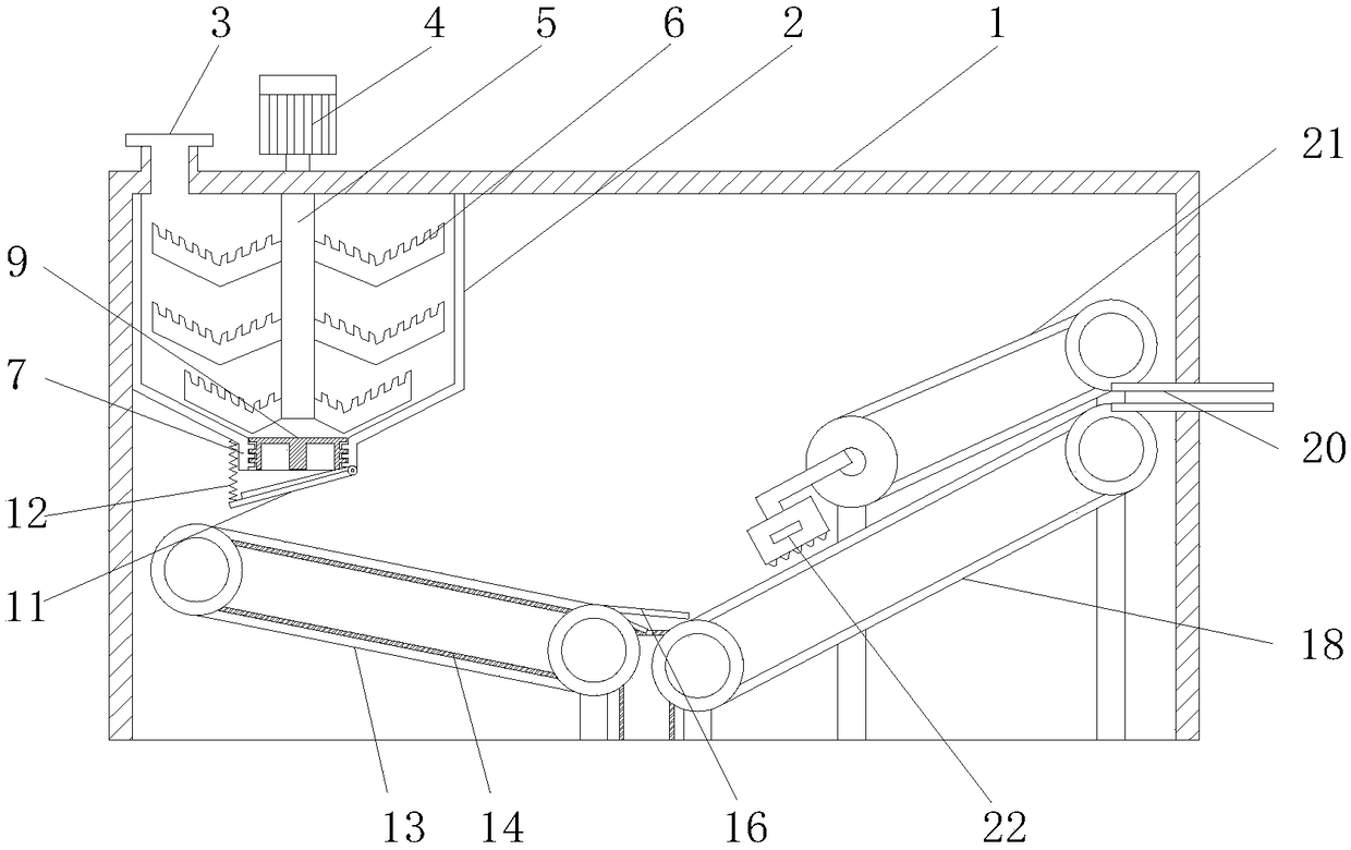
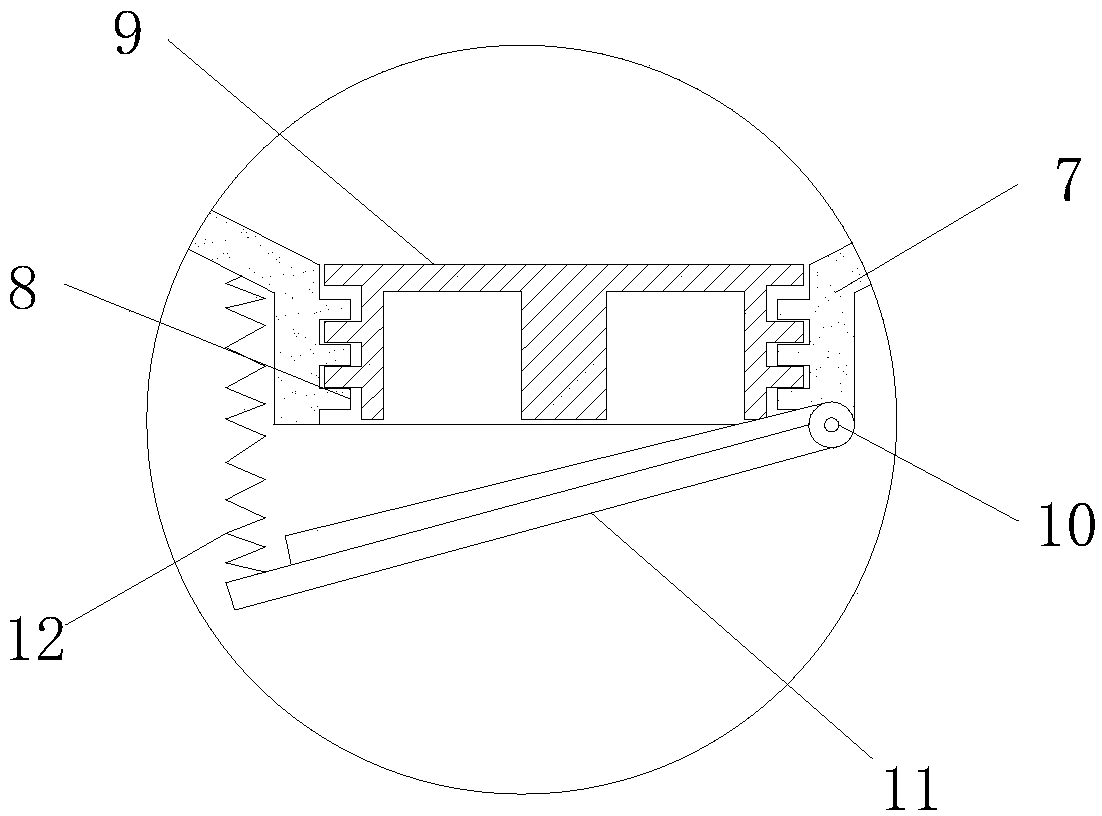
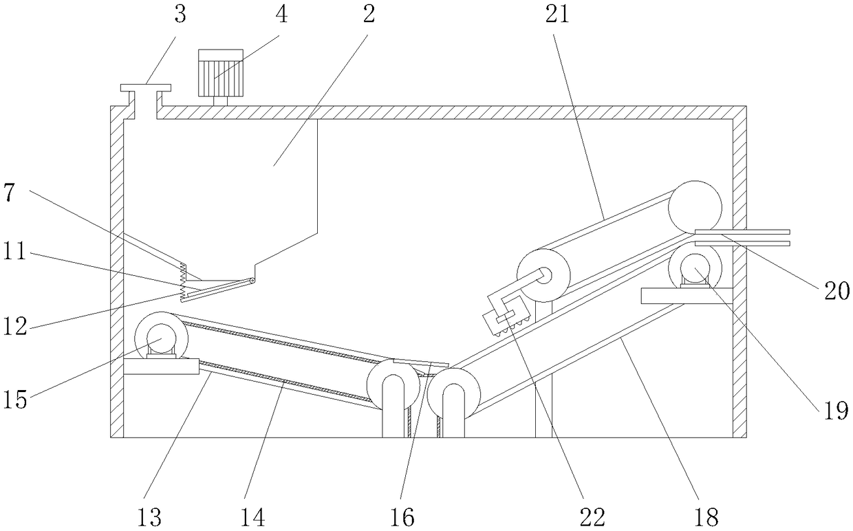
[0025] Such as Figure 1-4 As shown, the present invention provides a technical solution: a printing and dyeing sludge drying treatment device, including a shell 1, a tank body 2, a feed port 3, a first motor 4, a shaft 5, a stirring blade 6, and a discharge Port 7, bump 8, mud baffle 9, rotating shaft 10, drainage plate 11, spring 12, first conveyor belt 13, heating plate 14, second motor 15, connecting plate 16, groove 17, second conve...


PUM


Abstract

The invention discloses a dyeing sludge drying treatment device. The device comprises a shell body, wherein a tank body is fixed to the upper end of the left side of the interior of the shell body, the left side of the upper end of the tank body is provided with a feeding port, stirring blades are installed on the surface of a shaft rod, the lower end of the tank body is provided with a dischargehole, a boss is welded to the surface of the interior of the discharge hole, a flow guiding plate is fixed to the other end of a rotary shaft, a spring is fixed to the upper end of the left side of the flow guiding plate; a first conveyor belt is fixed to the left side of the lower end of the interior of the shell body, a heating plate is installed in the first conveyor belt; the left side of theupper end of a connection plate is provided with a groove, a second conveyor belt is installed on the right side of the connection plate, a squeezing roller is fixed to the upper end of the second conveyor belt, and a squeezing plate is installed on the left side of the squeezing roller. The dyeing sludge drying treatment device improves the stirring efficiency, accelerates reaction of sludge anda coagulant, is convenient for guiding the discharging direction of the sludge, can discharge and distribute uniformly, and is convenient for achieving evenness and high efficiency of squeezing.

Description

technical field [0001] The invention relates to the technical field of fabric processing, in particular to a printing and dyeing sludge drying treatment device. Background technique [0002] During the processing of the fabric, it needs to be printed and dyed, and then the sludge needs to be treated. The printing and dyeing sludge treatment first needs to be mixed with a coagulant, then dehydrated, and finally squeezed and dried. It is a machine that applies mechanical force on one side of the filter medium to achieve filtration. It is mainly used for solid-liquid separation of sludge. After the sludge is dried, it is convenient for landfill disposal. [0003] Many existing sludge drying treatment devices have low mixing and dehydration efficiency, and the uneven distribution of sludge inside the device may easily lead to uneven pressing, resulting in high water content after drying treatment, and the drying effect is not ideal. Contents of the invention [0004] (1) Solv...

Claims


Application Information

Patent Timeline
IPC IPC(8): C02F11/14C02F11/121C02F11/13C02F103/30
CPCC02F11/12C02F11/121C02F11/14C02F2103/30
Inventor 周文礼
Owner 嘉兴市乔兰服饰有限公司
Why Eureka
Try Eureka