Centrifugal pump

A centrifugal pump and pump body technology, applied in the field of centrifugal pumps, can solve problems such as low operating efficiency, increased friction surface, increased friction loss, etc., and achieve the effects of improving operating efficiency, increasing vacuum degree, and increasing flow

Inactive Publication Date: 2006-04-12
陈瑜
View PDF0 Cites 3 Cited by
  • Summary
  • Abstract
  • Description
  • Claims
  • Application Information

AI Technical Summary

Problems solved by technology

[0006] 4. The axial width at the outlet of the outer diameter of the traditional impeller becomes smaller, and the center of the outlet is not at the center of the volute, which will cause the following disadvantages. The former cannot make full use of the kinetic energy of the water leaving the outer diameter of the impeller, because the narrow water spray How can the impulsive movement of large-diameter water, so the kinetic energy can only be converted into static pressure water, and then the static pressure will press the water to the outlet pipe
And because the axial width of the outlet of the impeller is not in the center of the volute, the fluid will spirally rotate horizontally along one side of the volute flow channel. For those pumps with small flow and high lift, this phenomenon will be particularly serious. So a lot of useless work wasted
[0007] From the above analysis, it can be seen that for those pumps with large flow and low head, the above phenomena are relatively small, but still have an impact.
Especially for impellers with a large number of blades, the vortex of the negative pressure on the back of the blades is small, but the blades are too dense, the friction surface increases, and the friction loss is also increased.
It will have a great impact on those pumps with small flow and high head. It is worth mentioning that it is easy to transport the pulp pumps, sediment pumps and all liquids containing solids and suspended substances that are widely used in industrial production. The pump whose impeller water inlet is blocked, because of its small number of blades, will have a greater impact on the above phenomenon, so its operating efficiency will be very low

Method used


Image

  • Centrifugal pump
  • Centrifugal pump
  • Centrifugal pump

Examples


Embodiment Construction

[0031] The present invention will be described in further detail below in conjunction with the accompanying drawings.

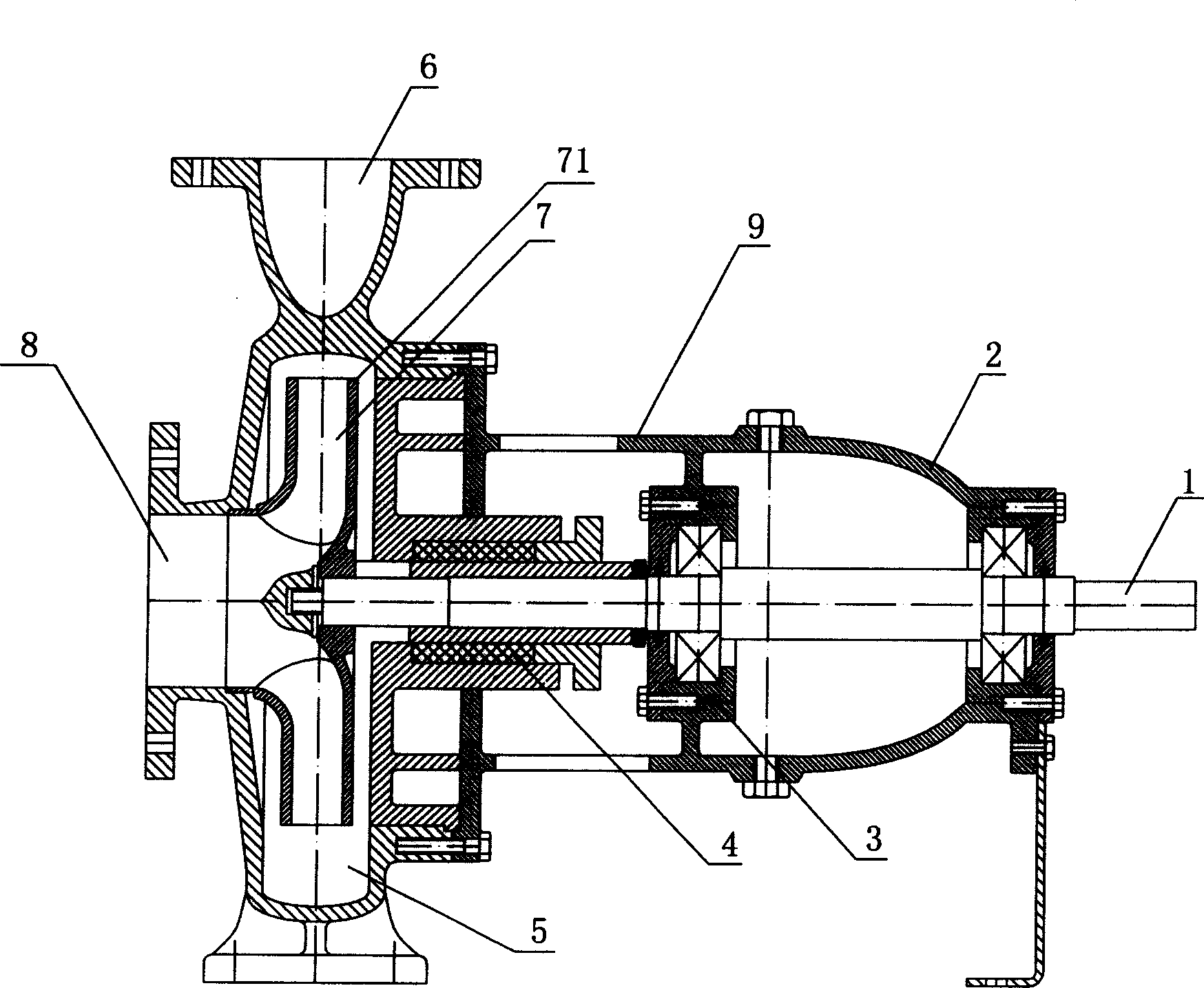
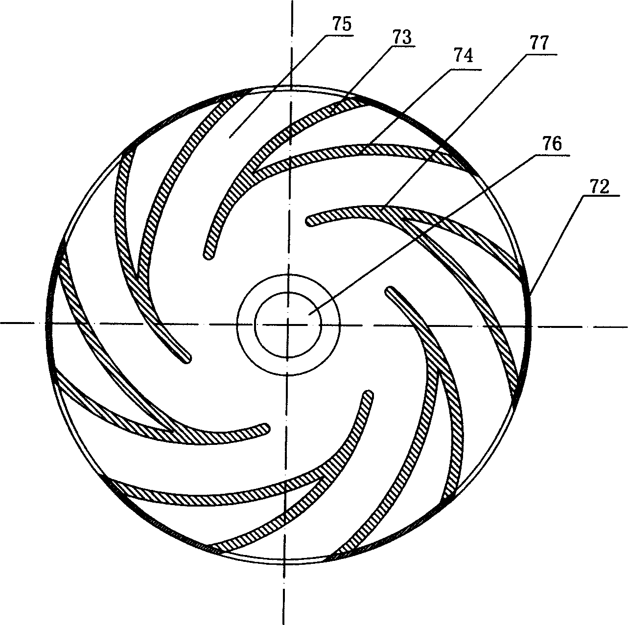
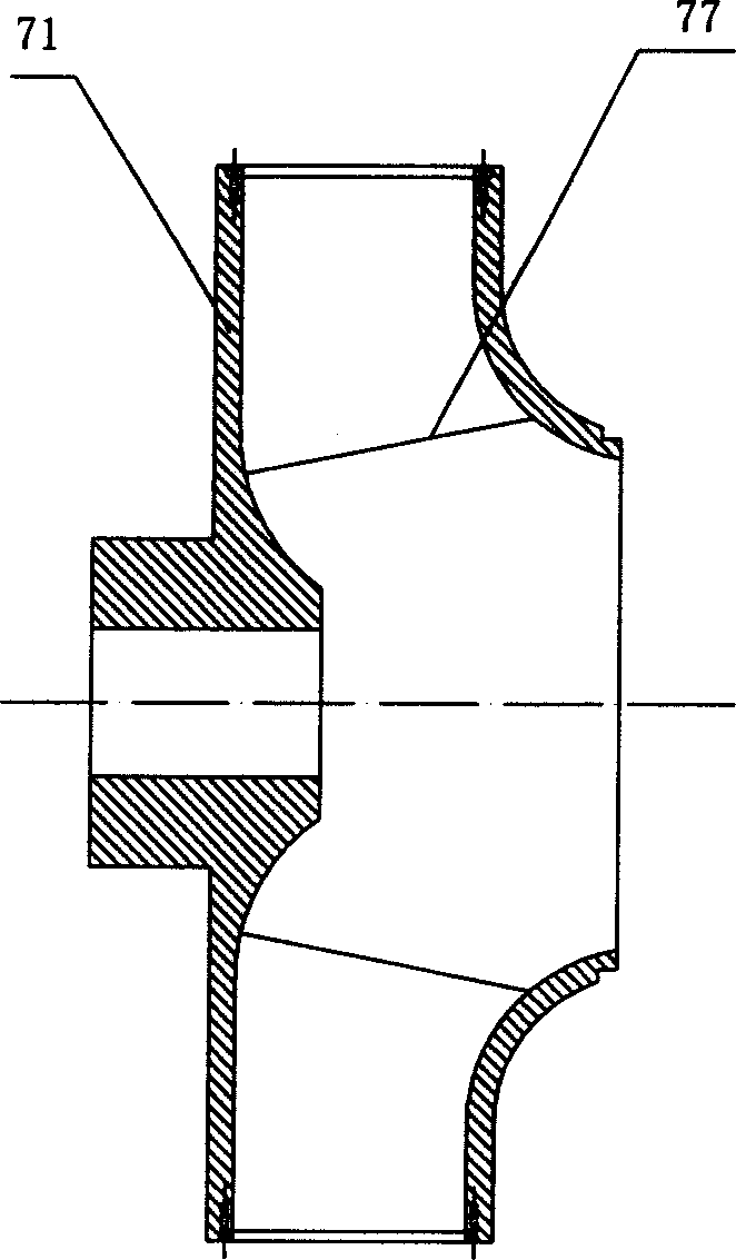
[0032] Such as figure 1 , figure 2 and image 3 As shown, the centrifugal pump of the present invention comprises a pump body 9, a pump shaft 1 and an impeller 7, and the inside of one end of the pump body 9 is cavity-shaped to form a volute 5, and the volute 5 passes through the flow channel 75 of the impeller 7 and the pump The water inlet 8 opened on the body 9 communicates with the water outlet 6. The other end of the pump body 9 is equipped with a pump shaft 1. The pump shaft 1 is fixed in the pump body 9 through the bearing seat 2 and the bearing 3, and is sealed by the sealing layer 4. It is separated from the volute 5 at the other end in the pump body 9 to prevent water from flowing in. The impeller 7 is arranged in the volute 5 of the pump body 9 and installed on the pump shaft 1. The impeller 7 includes a wheel casing 76, a web 71 and two or mo...


PUM


Abstract

A centrifugal pump is composed of a main body with a volute cavity at its one end, a mainshaft installed at another end of main body, and a blade wheel installed on said mainshaft and contained in said volute cavity. Said blade wheel consists of hub, webs and two or more blades installed to webs and composed of primary and secondary blades linked by a sealing plate. Its advantages are high efficiency and low energy consumption.

Description

technical field [0001] The present invention mainly relates to a centrifugal pump. Background technique [0002] Since the advent of the centrifugal pump, the structure of the impeller, the core component of its work, has been based on a hypothetical theoretical basis, which is to make the number of impeller blades infinitely large, and the thickness of the blades is infinitely small, so as to eliminate the vortex of water in the impeller. In order to improve the working efficiency of the whole centrifugal pump to achieve the effect of energy saving. But in the actual structure, the number of blades of the impeller is very few, that is, under the effective volume of the overall design of the centrifugal pump, the number of blades is limited, and the blades also have a certain thickness. Because of the discrepancy between theory and reality, people have generally believed that the consumption of these useless efforts is normal for centuries. Taking water pumps as an example...

Claims


Application Information

Patent Timeline
Patent Type & Authority Applications(China)
IPC IPC(8): F04D29/24
Inventor 陈永生陈瑜
Owner 陈瑜
Why Eureka
Try Eureka