Image processing apparatus, its calibration method, and image processing method

An image processing device and correction table technology, applied in image communication, electrical recording technology using charge graphics, equipment using electrical recording technology using charge graphics, etc., can solve the problems of a large number of test charts, increasing user burden and cost, etc., To achieve the effect of preventing concentration changes

Inactive Publication Date: 2006-04-12
CANON KK
View PDF1 Cites 11 Cited by
  • Summary
  • Abstract
  • Description
  • Claims
  • Application Information

AI Technical Summary

Problems solved by technology

However, this method requires a large number of test charts, thereby increasing the user's burden and cost

Method used


Image

  • Image processing apparatus, its calibration method, and image processing method
  • Image processing apparatus, its calibration method, and image processing method
  • Image processing apparatus, its calibration method, and image processing method

Examples


no. 1 example

[0033] [device structure]

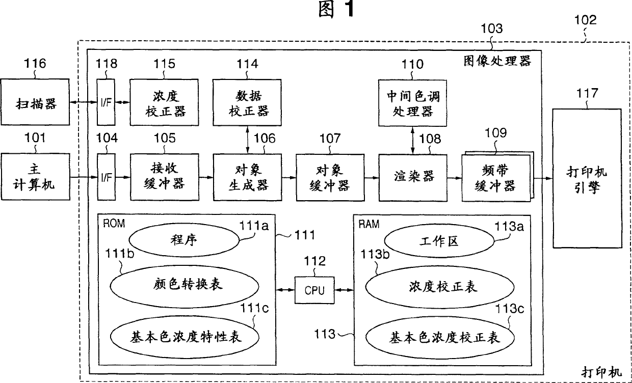
[0034] FIG. 1 is a block diagram showing the configuration of an image forming apparatus (hereinafter referred to as "printer") of a first embodiment.

[0035] The host computer 101 outputs print information representing color data, text data, graphics data, image data, and the number of print copies to the printer 102, and is requested to execute print processing. The scanner 116 scans a patch pattern (described later), and outputs scanned image data to the printer 102 .

[0036] The printer 102 is roughly divided into an image processor 103 and a printer engine 117 for forming an image based on an image signal output from the image processor 103 .

[0037] The CPU 112 of the image processor 103 performs various processes and judgments, and controls components (described later) of the image processor 103 in accordance with programs stored in the ROM 111 . The ROM 111 stores a color conversion table 111b and a basic color density characteristic ta...

no. 2 example

[0088] Image processing according to a second embodiment of the present invention will be described below. Note that the same reference numerals denote the same components as those in the first embodiment, and detailed descriptions of these components will be omitted.

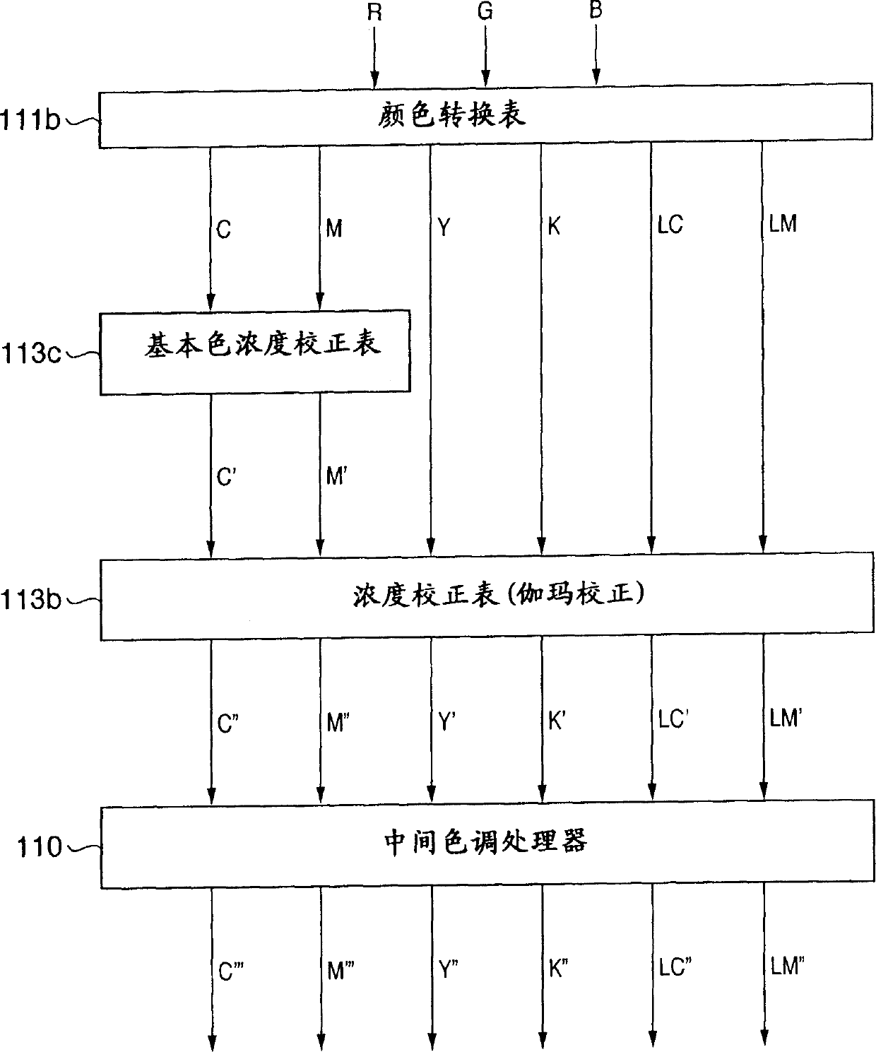
[0089] In the first embodiment, as shown in FIG. 4, color processing is performed by establishing the basic color density correction table 113c and the density correction table 113b as independent tables. However, since these two tables are both linear lookup tables, they are combined into one table (for example, density correction table 113b) in step S805 shown in FIG. Color handling shown in .

[0090] FIG. 21 shows an example of the density correction table 113b combined with the basic color density correction table 113c. In FIG. 21, (a) shows the density correction table 113b created in step S803, (b) shows the basic color density correction table 113c created in step S804, and (c) shows the combined dens...


PUM


Abstract

A stable, unicolor intermediate density region in a four-color system is defined by mixing dark and light color recording materials in a six-color system. For this reason, a calibration for the four-color system cannot correct density variations, and a pseudo-contour due to discontinuity of tones is produced in a transition region from the light color recording materials to dark color recording materials included in the intermediate density region, thus considerably deteriorating image quality. The tone characteristics of respective colors are obtained from a patch pattern of respective color recording materials, and a tone correction table used to correct the tones of the respective colors is created on the basis of the tone characteristics of the respective colors. The tone characteristics of primary colors calculated from the tone characteristics of the respective colors with reference to a basic color density characteristic table indicating the density characteristics when the dark and light color recording materials are mixed. A basic color density correction table used to correct the tone characteristics of the primary colors is created with reference to the basic color density characteristic table and the density correction table.

Description

technical field [0001] The present invention relates to an image processing device, a calibration method thereof, and an image processing method, and more particularly, to using dark and light color recording materials having the same hue value but different lightness values Calibration and image processing of the image processing device. Background technique [0002] In an electrophotographic image forming apparatus, density correction (calibration) required to eliminate tint variation due to density aging (density variation) is performed in the following two stages. Initially, a test pattern is formed in the device, the density of the test pattern is measured by a sensor in the device, and the transfer voltage is adjusted so that the maximum density (solid density) takes a specified density value. Then, a test pattern including a halftone pattern is printed on printing paper, and a device such as a scanner is used to measure the density of the test pattern, thereby obtain...

Claims


Application Information

Patent Timeline
Patent Type & Authority Applications(China)
IPC IPC(8): G03G15/08G03G15/00G03G21/14
CPCH04N1/6033
Inventor 橿渕洋一
Owner CANON KK
Why Eureka
Try Eureka