Method of focal plane array image space-time changing based on fibre-optical coupled

A technology of focal plane array and optical fiber coupling, which is applied in the direction of TV system adapting to optical transmission and cable transmission adaptation, can solve the problems of slow progress in the research of longer line array devices, and achieve reduced system complexity, good robustness, and reduced The effect of process requirements

Active Publication Date: 2006-04-12
SHANGHAI INST OF TECHNICAL PHYSICS - CHINESE ACAD OF SCI
View PDF0 Cites 20 Cited by
  • Summary
  • Abstract
  • Description
  • Claims
  • Application Information

AI Technical Summary

Problems solved by technology

Restricted by various factors, the research on

Method used


Image

  • Method of focal plane array image space-time changing based on fibre-optical coupled
  • Method of focal plane array image space-time changing based on fibre-optical coupled
  • Method of focal plane array image space-time changing based on fibre-optical coupled

Examples


Embodiment Construction

[0018] The following is based on Figure 3-Figure 9 A preferred embodiment of the present invention is given and described in detail so as to further provide the technical details of the present invention and make it easy to understand the method features and functional characteristics of the present invention, but it is not used to limit the scope of the present invention.

[0019] In order to restore the original image, the system image obtained by the system needs to go through three processing steps: space transformation, integral algorithm and time transformation. The specific operations are as follows:

[0020] 1. Space transformation

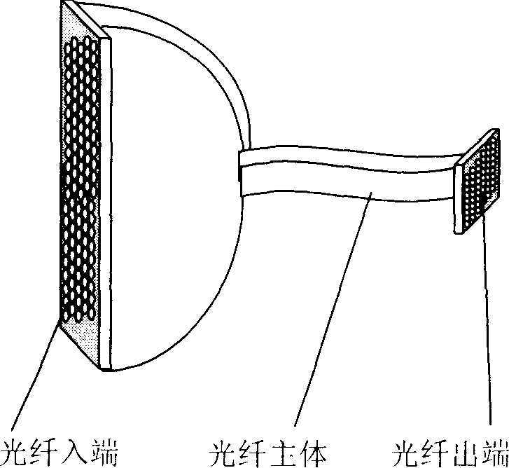
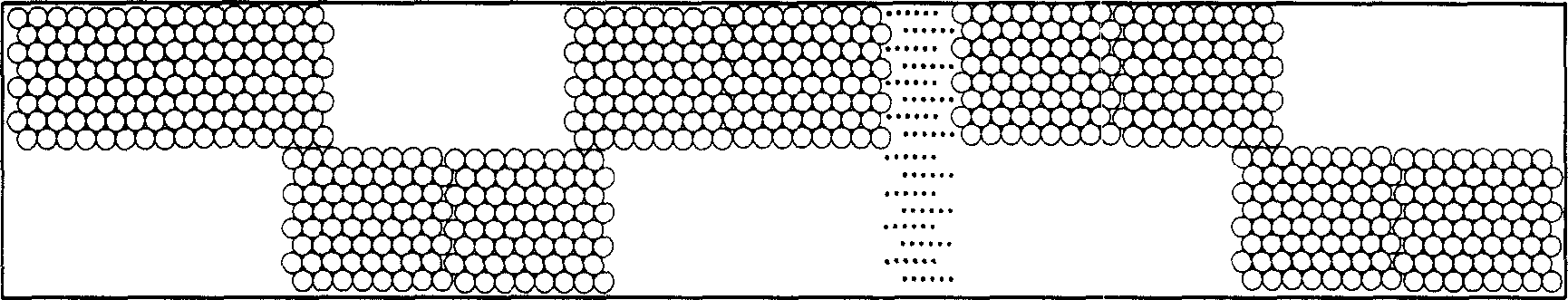
[0021] The purpose of space transformation is to restore the area array image of the fiber outlet 3 to the line array image of the fiber inlet 1, which includes two processes of image preprocessing and fiber center positioning. The main steps are:

[0022] ①Before the system scans and images, it first images the object used for calibrati...


PUM


Abstract

A method for converting focal plane array image space ¿C time includes obtaining picture of optical fiber positioning to position each optical fiber center by using scan system to scan uniform white scale object with sufficient brightness at each time of imaging first, then obtaining series image by scanning actual objects and finally reviving them to be original image through space ¿C time conversion, integral operation and time conversion.

Description

technical field [0001] The invention relates to a space transformation, time transformation and related image processing method for image restoration in an ultra-high-resolution large-scale infrared photoelectric imaging system. Background technique: [0002] The design and processing of the ultra-long line detector is the core technology of the ultra-high resolution imaging system. France Sofradir has successfully developed a 3,000 yuan mid-wave infrared detector with superior performance. In 2003, China successfully developed the medium wave 2048 yuan infrared detector. Restricted by various factors, the research progress of longer line devices is slow. However, the small-scale area array infrared focal planes 128×128 and 320×240 have mature products. [0003] In recent years, the optical fiber bundle for image transmission has made great progress, and has applications in spectroscopic instruments, medical equipment, and missile warning receivers. In 1999, Beijing Glas...

Claims


Application Information

Patent Timeline
IPC IPC(8): H04N7/22
Inventor 安博文方中华孙胜利陈桂林
Owner SHANGHAI INST OF TECHNICAL PHYSICS - CHINESE ACAD OF SCI
Why Eureka
Try Eureka