Inertia drive torque transmission level control and engine starter incorporating same

A technology for torque transmission and starter, which is applied in the direction of engine starting, starting device with manual crank, starting device with mechanical power storage, etc., which can solve problems such as increasing the cost of the drive

Inactive Publication Date: 2006-04-12
史密斯宇宙公司
View PDF0 Cites 6 Cited by
  • Summary
  • Abstract
  • Description
  • Claims
  • Application Information

AI Technical Summary

Problems solved by technology

The wide, uncontrolled torque range over which this clutch plate will slip increases the cost of owning such a drive due to increased wear if slip occurs at lower torque values, engine and starting elements when torque levels are too high excessive stress on

Method used


Image

  • Inertia drive torque transmission level control and engine starter incorporating same
  • Inertia drive torque transmission level control and engine starter incorporating same
  • Inertia drive torque transmission level control and engine starter incorporating same

Examples


Embodiment Construction

[0029] As noted above, one problem with conventional engine starter inertia drives is the uncontrollable nature of the torque for clutch plate slip. Such uncontrollable torque values ​​lead to increased wear of the clutch plates, if the torque values ​​at which slip occurs are too low, and to increased stress on starter and engine components if the torque values ​​at which slip occurs are too high. An additional problem associated with this conventional engine starter drive is the cost of the six compression springs required to maintain force on the clutch stack. In order to overcome these problems, the focus of research and development is that the traditional engine starter driver cannot control the torque generated by the slippage to the engine starter inertial driver of the present invention in an acceptable and narrow range.

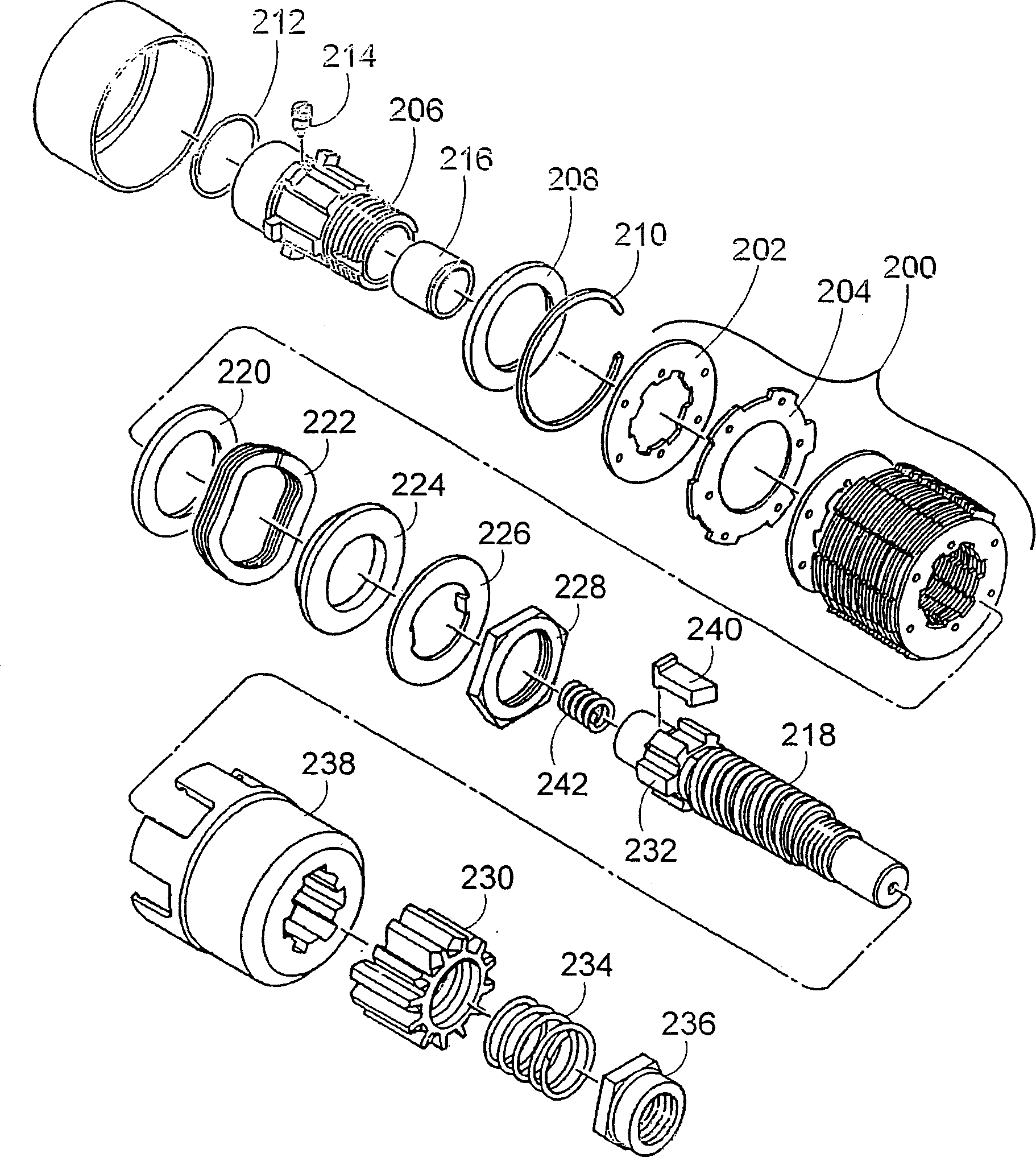
[0030] refer to figure 1 , illustrates an embodiment of an exploded three-dimensional form according to the invention. Such as figure 1 As can ...


PUM


Abstract

An engine starter inertia drive that includes a torque transmission level control mechanism is presented. Such torque transmission level control is provided by removing the variations in clutch plate compression force conventionally introduced by the shock absorbing meshing spring of the engine starter inertia drive. This is accomplished by repositioning the compression forces such that they are contradicted by a combination of the meshing spring force and the frame reaction of the engine starter. In this way, variations in the meshing spring force are compensated by equal and opposite variations in the frame reaction force to maintain the clutch plates in position. Preferably, a single wave spring is used to provide the pressure spring force on the clutch plates.

Description

technical field [0001] The present invention relates generally to engine starter inertia drives and, more particularly, to torque transmission controllers for engine starter inertia drives. Background technique [0002] The success and profitability of many industries is directly dependent on the ability and need to operate equipment reliably. The downtime of equipment necessary to modify or replace components makes operating costs unacceptable and reduces the ability to generate revenue from operating that piece of equipment. Therefore, it is extremely important for all components used in such equipment to be robust, reliable and cost-effective. It is also important for such components to provide controlled operation of performing their function without adversely affecting the device of which it is a component. [0003] In many industries, such as mining, power generation, oil, gas and marine, heavy duty engine drives such equipment. Such engines may have cylinder displa...

Claims


Application Information

Patent Timeline
Patent Type & Authority Applications(China)
IPC IPC(8): F02N1/00F02N5/04F02N15/02F02N15/06
CPCF02N15/06F02N5/04F02N15/025Y10T74/134Y10T74/133Y10T74/131F02N1/00F02N15/00
Inventor 大卫·W·爱柯德约翰·M·伯克希姆
Owner 史密斯宇宙公司
Why Eureka
Try Eureka