Jig and method of manufacturing a display device using the same

A display device and fixture technology, which is applied in the direction of workpiece clamping devices, manufacturing tools, hand-held tools, etc., can solve the problems of lower production efficiency and wear of the flexible circuit film of the backlight component, so as to increase production, improve assembly efficiency, Reduces the effect of defective products

Inactive Publication Date: 2006-04-26
SAMSUNG ELECTRONICS CO LTD
View PDF0 Cites 11 Cited by
  • Summary
  • Abstract
  • Description
  • Claims
  • Application Information

AI Technical Summary

Problems solved by technology

However, the use of fixing jigs requires workers to load and unload the unfinished backlight assembly multiple times, which reduces production efficiency and causes wear on the flexible circuit film or other parts of the backlight assembly

Method used


Image

  • Jig and method of manufacturing a display device using the same
  • Jig and method of manufacturing a display device using the same
  • Jig and method of manufacturing a display device using the same

Examples


Embodiment Construction

[0020] The present invention will be described more fully hereinafter with reference to the accompanying drawings and examples. However, the invention may be embodied in many different forms and should not be construed as limited to the embodiments set forth herein. The examples are given for the purpose of illustration only and not for the purpose of limiting the invention. Like reference numerals designate like or identical elements in this specification.

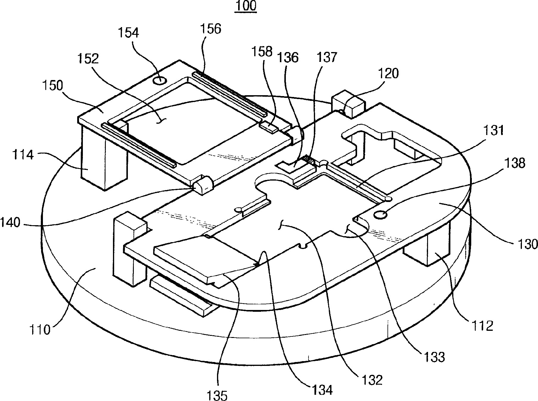
[0021] figure 1 is a perspective view of a jig according to an exemplary embodiment of the present invention.

[0022] refer to figure 1 , the jig 100 includes a stand 110 , a first hinge part 120 , a working plate 130 , a second hinge part 140 and a housing 150 .

[0023] The stand 110 may have, for example, a circular plate shape. Alternatively, the stand 110 may have various shapes, such as a rectangular plate shape. The stand 110 can be tilted to a predetermined angle to facilitate workers to operate. The stage...


PUM


Abstract

The invention provides a jig for manufacturing a display device. In one embodiment, the clamp includes a first hinge part for rotating the working board on which the backlight assembly is fixed, and a second hinge part for rotating the housing to fix the backlight assembly on the working board. A method of manufacturing a display device using the jig includes loading a backlight assembly on a working plate of the jig, mounting a main panel on the main portion of the backlight assembly, rotating the housing to fix the backlight assembly to the working plate, rotating the working plate, and The subpanel is mounted on the subsection of the backlight assembly. In various embodiments, the use of the jig can improve the efficiency of assembly, reduce the number of product defects, and increase the throughput of display devices.

Description

technical field [0001] The invention relates to a jig and a method of using the jig. In particular, the present invention relates to a jig for manufacturing a display device, and a method of manufacturing a display device using the jig. Background technique [0002] Typically, display devices are used in conjunction with various electronic devices, such as cell phones, digital cameras, notebook computers, monitors, and others. In particular, flat panel display devices such as liquid crystal displays (LCDs) have been widely used in various fields. [0003] In recent years, display devices capable of displaying images in two directions have been developed and used in conjunction with various electronic devices. Such a display device includes: a main panel displaying a main image; a sub panel displaying time, date, reception sensitivity or other information; and a backlight assembly providing light to the main panel and the sub panel. [0004] These display devices can be as...

Claims


Application Information

Patent Timeline
Patent Type & Authority Applications(China)
IPC IPC(8): B25B11/02B25B27/14
CPCG02F1/1303G02F1/133308Y10T29/49895Y10T29/53961G02F1/13
Inventor 李秉训
Owner SAMSUNG ELECTRONICS CO LTD
Why Eureka
Try Eureka