
Servo type volumetric flowmeter

A flowmeter and volumetric technology, applied in the field of servo-type volumetric flowmeters, can solve problems such as increased instrument error density and fluid leakage

Inactive Publication Date: 2006-04-26
OVAL CORP
View PDF0 Cites 1 Cited by
  • Summary
  • Abstract
  • Description
  • Claims
  • Application Information

AI Technical Summary

Problems solved by technology

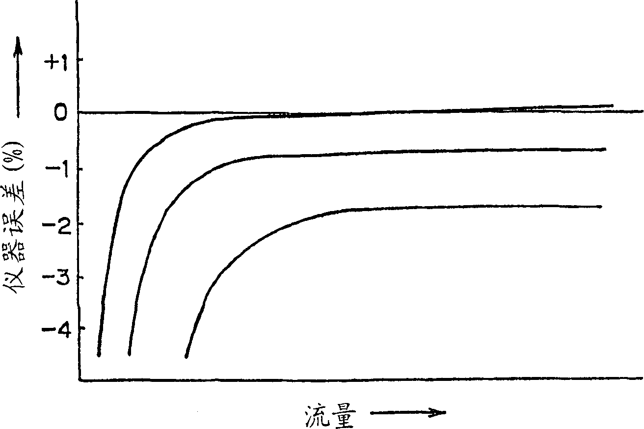
[0025] However, when the flow rate is actually measured with the prior art servo-type positive displacement flowmeter, in the small flow area, although the situation of the large negative instrument error in the prior art self-operated positive displacement flowmeter is improved, the The instrument errors will all become positive and show the characteristics of increasing with the increase of flow rate and density
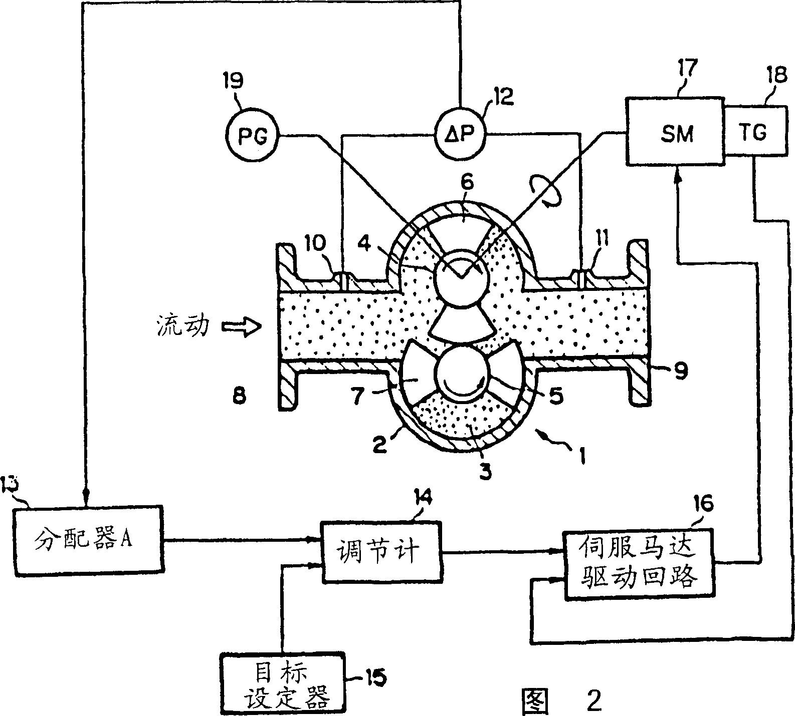
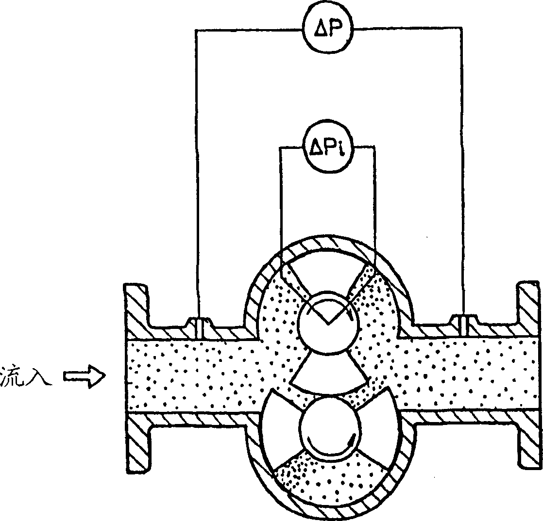
[0026] The reason for the positive instrument error is that in order to control the pressure difference loss between the outflow and the outlet of the positive displacement flowmeter so that there is no pressure difference, when the rotor is forcibly rotated by the servo motor, even if the positive displacement flowmeter The pressure loss ΔP between the outflow and inflow ports of the meter is zero. Since the pressure on the front side in the direction of rotor rotation in the metering chamber increases and the pressure on the back side decreases, a pressure difference ΔPi will be generated between the front and back sides in the direction of rotor rotation. , due to the gap between the housing and the rotor, the pressure difference ΔPi will cause leakage of the measured fluid from the outflow side to the inflow side

Method used


Image

  • Servo type volumetric flowmeter
  • Servo type volumetric flowmeter
  • Servo type volumetric flowmeter

Examples


Embodiment Construction

[0036] Generally, when the fluid flows through the positive displacement flowmeter, when a pressure loss of ΔP occurs at the pressure difference detection position sufficiently away from the rotor, the formula

[0037] ΔP=ΔP1+ΔP2

[0038] established. Here, ΔP1 is the pressure loss required to rotate the rotor. Since it is directly related to the leakage inside the flowmeter, it is called the internal pressure loss. In addition, ΔP2 is the pressure loss consumed by the fluid flowing through the flowmeter. Since it is not directly related to leakage, it is called external pressure loss.

[0039] In a positive displacement flowmeter with a pair of built-in rotors, relative to the pressure difference ΔPi before and after the rotor related to the leakage inside the flowmeter, the leakage inside the flowmeter per unit time is Δq, when the viscosity of the fluid is μ, the flow rate is When Q is expressed by the following formula,

[0040] Δq=ka·(ΔPi / μ)+kb·Q...(1)

[0041] Among th...


PUM


Abstract

A servo-type volumetric flowmeter, which includes: a metering chamber arranged in a flow path, a pair of first and second rotors that rotate in the metering chamber and flow out a certain volume of fluid each time they rotate, and detect the aforementioned metering chamber The first differential pressure gauge for the pressure difference between the upstream side and the downstream side of the flow path is arranged in series in the aforementioned flow path, and the throttling mechanism for narrowing the flow path is used to detect the pressure difference between the upstream side and the downstream side of the throttling mechanism. The second differential pressure gauge, and use the differential pressure signal from the second differential pressure gauge to adjust the differential pressure signal from the first differential pressure gauge to obtain a target value, and follow the target value to drive the first or the first differential pressure gauge Servo mechanism for any one of the two rotors.

Description

technical field [0001] The present invention relates to a servo-type volumetric flowmeter, and more specifically, to a servo-type volumetric flowmeter having an excellent characteristic that an instrument error is almost zero in a small flow area to a large flow area. Background technique [0002] A representative positive displacement flowmeter with a pair of rotors is a kind of metering chamber, in which a pair of rotors are rotated using the pressure difference of the fluid. The measured fluid flows out according to the rotation of the rotor, and the flow meter calculates the flow rate from the number of revolutions of the rotor. [0003] That is, ideally, a volume of the fluid to be measured corresponding to the reference volume is discharged in proportion to the rotation of the rotor. [0004] However, in an actual positive displacement flowmeter, in order to allow the rotor to rotate, a slight gap is provided between the rotor and the measurement chamber, and the roto...

Claims


Application Information

Patent Timeline
Patent Type & Authority Applications(China)
IPC IPC(8): G01F11/00
Inventor 三角胜夫小川胖小野精悟半田龙太
Owner OVAL CORP
Learn More