
Antenna connector structure and its manufacturing process

An antenna connector and manufacturing process technology, applied in connection, two-part connection device, assembly/disassembly of contacts, etc., can solve problems such as insufficient structural strength, high insertion loss, inability to withstand tensile and torsional damage tests, etc.

Inactive Publication Date: 2006-04-26
皓腾工业股份有限公司
View PDF0 Cites 1 Cited by
  • Summary
  • Abstract
  • Description
  • Claims
  • Application Information

AI Technical Summary

Problems solved by technology

[0007] Therefore, although the second antenna connector 2 made by the second known manufacturing process can shorten the distance, it still has the following defects: first, it The structural strength of the ring 27 will be insufficient, and it will not be able to withstand the tensile and torsion damage tests; secondly, its electrical characteristics will be too large due to its side port 222, resulting in high insertion loss
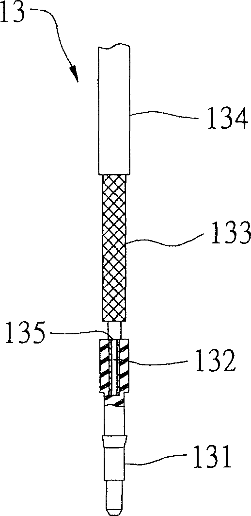
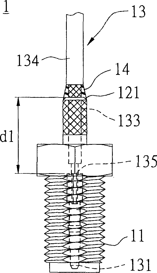
[0008] In other words, the first known manufacturing process that does not use clamps will cause excessive radiation and high insertion loss due to the excessively large internal aperture of the connecting shaft 12, and also cause the ring welding part 14 and welding The distance d1 between points 135 is too long, which also leads to excessive radiation and high insertion loss
However, even though the second known manufacturing process uses clamps to press and shorten the distance, it still has insufficient structural strength and lacks resistance to tensile and torsional damage tests, and because of the side opening 222 is too large to cause high insertion loss
Therefore, the electrical characteristics and structural strength of these two known manufacturing processes cannot meet the requirements

Method used


Image

  • Antenna connector structure and its manufacturing process
  • Antenna connector structure and its manufacturing process
  • Antenna connector structure and its manufacturing process

Examples


Embodiment Construction

[0073] In order to further understand the features and technical content of the present invention, please refer to the following detailed description of the present invention and the accompanying drawings.

[0074] see Figure 6 , 8 , As shown in Figure 9, the present invention provides a structure and manufacturing process of an antenna connector. The structure of the antenna connector includes: a main body 3, an insulating material 4, a pin 5, a connecting shaft 6, and a cable7.

[0075] Wherein, one end shaft of the pin 5 is provided with an insertion hole 53, and the end and the roughly middle section of the pin 5 are respectively provided with first and second interference parts 51, 52, and the first interference part 51 is embossed. Handling to prevent the pin 5 from rotating, the second interference part 52 is a round barb for the car to prevent the pin 5 from retreating; the center of the insulating material 4 has a center hole opposite to the pin 5 for insertion, A...


PUM


Abstract

The structure of an antenna adapter comprises: a main body with an embedded insulation material, a pin inserted in the insulation material, a cable with core wire welded with one pin end and screen wire both decorticating and tin plating, a shaft with base in top of main body, pole with said screen wire, and shaft hole crossed by said cable. The manufacture technique comprises: inserting the pin into insulation material, welding the shaft with cable, and assembling in main body end to compress the pole and screen wire together by clamp tool.

Description

technical field [0001] The present invention relates to a "structure and manufacturing process of an antenna connector", in particular to an antenna connector which is used to connect an antenna and is required to reduce its insertion loss to have better electrical characteristics and its manufacturing process. Background technique [0002] For any electrically connected connector, the focus is nothing more than construction and electrical characteristics, and the same is true for antenna connectors. [0003] The size of each part of the antenna connector must meet the design specifications, such as: the main body of the connector, the ratio of the inner and outer diameters of the pins to the insulating material, and the length of the pins, etc. In addition, according to the impedance characteristics of the coaxial line, the sparser the outer braided wire, the greater the radiation (Radiation), and the greater the insertion loss (InsertionLoss); relatively, the denser the o...

Claims


Application Information

Patent Timeline
IPC IPC(8): H01R43/20H01R24/38H01R43/00
Inventor 黄春烟
Owner 皓腾工业股份有限公司
Learn More