Electric power tool

A power tool and action technology, applied in the direction of manufacturing tools, striking tools, lightweight impact tools, etc., can solve the problems of increased assembly time, poor operability, and increased number of parts, and achieves excellent operability and reliability. Reduced assembly time and reduced manufacturing costs

Inactive Publication Date: 2006-05-03
MAKITA CORP
View PDF1 Cites 39 Cited by
  • Summary
  • Abstract
  • Description
  • Claims
  • Application Information

AI Technical Summary

Problems solved by technology

[0011] When there are many selectable action modes like this, it is necessary to separately operate the impact switching member for switching the impact mode and the drilling mode, the clutch switching member and the vibration switching member for switching the drilling mode to the clutch mode or the vibration drilling mode, thereby Poor operability and prone to m

Method used


Image

  • Electric power tool
  • Electric power tool
  • Electric power tool

Examples


Embodiment Construction

[0048] Embodiments of the present invention will be described below based on the drawings.

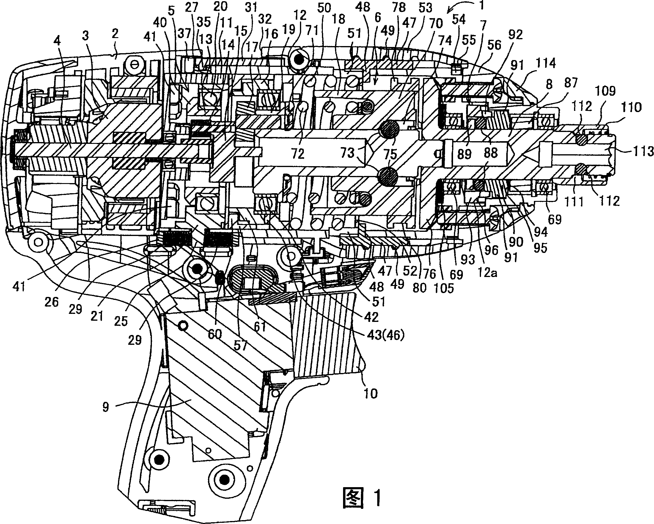
[0049] Fig. 1 is a longitudinal sectional view showing an example of an electric tool, that is, an impact screwdriver. The impact type screwdriver 1 is at the rear of a main body casing 2 composed of a pair of left and right half-cut casings (the right side of Fig. 1 is referred to as the front) A motor 3 is accommodated, and a planetary gear reduction mechanism 5 with a clutch mechanism, a striking mechanism 6, and a vibration mechanism 7 are respectively built in the front of the motor 3, so that the hammer anvil 8 coaxial with the motor shaft 4 of the motor 3 is forward protrude. 9 is a switch of the drive circuit of the motor 3, and 10 is a trigger which turns on the switch 9 by pressing operation.

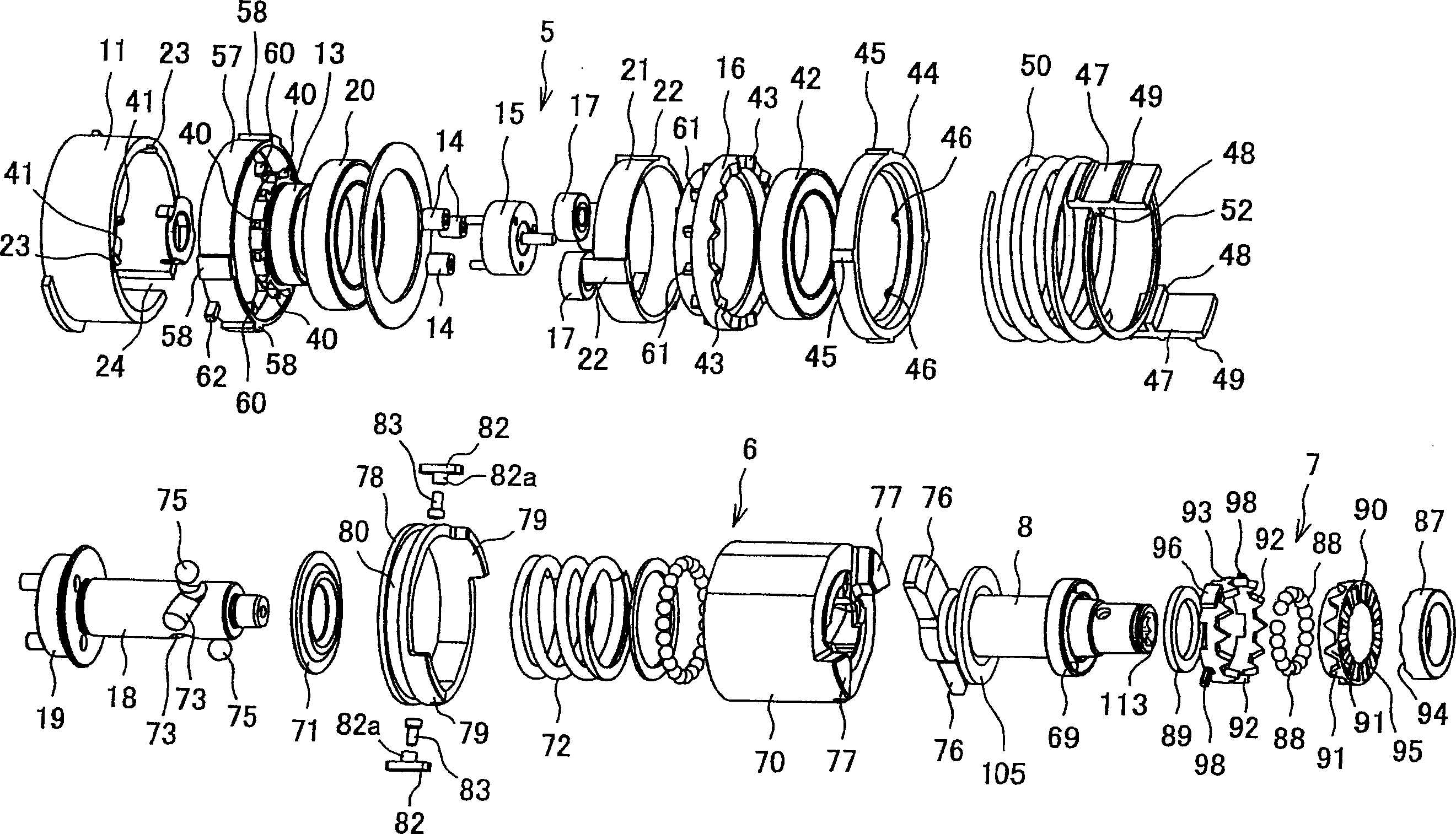
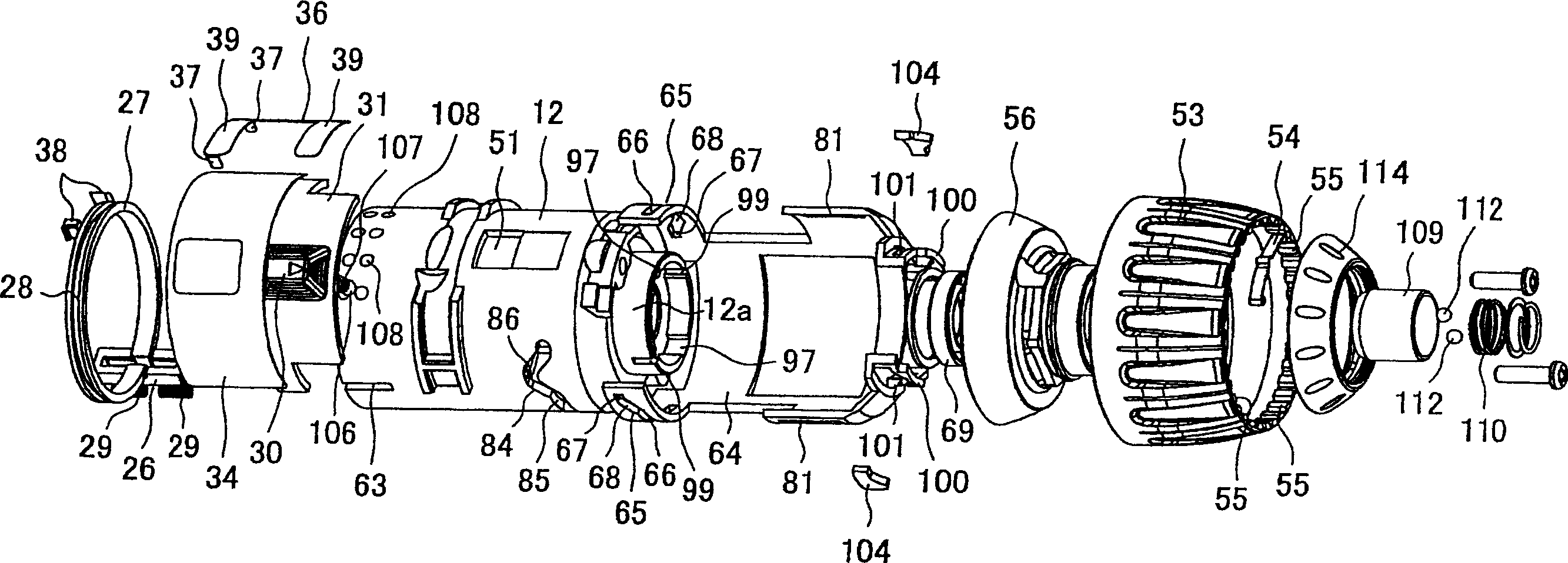
[0050] at the same time as figure 2 , 3 As shown, the planetary gear reduction mechanism 5 is accommodated inside a cylindrical motor bracket 11 and a cylindrical gear box 12. The m...


PUM


Abstract

An electric power tool capable of selecting an operation mode with good operability without risk of erroneous operation even though there are many operation modes. The gear box (12) in the housing respectively has: the clutch switching groove (65) engaged with the operation protrusion (62) of the clutch switching handle (57); ) of the notch (81) of the guide body (82) of the stepped pin (83) engaged; the vibration switching groove (101) engaged with the operation protrusion (98) of the vibration switching handle (93), and the The integrated rotary position of the switching plate (31) can change the combined switching box (64) of the sliding position of each switching member, and use the switching button (30) to rotate and operate the switching plate (31) and the switching box (64) from the outside of the housing, so that Only the operation of one switch button (30) can select all action modes of drilling mode, impact mode, vibration drilling mode and clutch mode.

Description

technical field [0001] The present invention relates to an electric power tool capable of giving intermittent blows or vibrations in the axial direction to an output shaft protruding from the front of a casing by selecting an operation mode. Background technique [0002] As an electric tool, for example, an impact tool described in Patent Document 1 and the like are known. Here, the rotation of the output shaft of the motor is transmitted to the drive shaft inside the housing through the planetary gear reduction mechanism. The arm of the anvil (output shaft) protruding from the front of the main body case is engaged to transmit the rotation of the drive shaft to the anvil via the hammer. When the load on the hammer anvil is high, the hammer moves backward due to the rotation of the ball, and the engagement with the arm of the hammer anvil is temporarily released, and the coil spring advances again to engage with the arm again. The movement of the hammer generates intermitt...

Claims


Application Information

Patent Timeline
IPC IPC(8): B25F3/00B23B45/16B23Q5/12B25D16/00
Inventor 古田岳文
Owner MAKITA CORP
Why Eureka
Try Eureka