Fluid mixer

A fluid mixing and fluid technology, applied in fluid mixers, mixers, mixing methods, etc., can solve the problems of lower mixing ratio accuracy, inability to mix ratio mixing, and lower mixing ratio accuracy

Inactive Publication Date: 2006-05-03
ASAHI YUKIZAI KOGYO CO LTD
View PDF1 Cites 18 Cited by
  • Summary
  • Abstract
  • Description
  • Claims
  • Application Information

AI Technical Summary

Problems solved by technology

[0005] (1) When a throttle such as a nozzle for supplying to the use contact is provided on the downstream side end of the linear mixer 114 of the mixing passage 113, foreign matter such as air bubbles adheres to the nozzle and the hole portion The pressure on the downstream side of 104, 110 increases, and the pressure fluctuation of the linear mixer 114 exceeds the pressure fluctuation, so that the holes 104, 110 cannot cope with the pressure fluctuation, the flow rate decreases, and the accuracy of the mixing ratio decreases.
[

Method used


Image

  • Fluid mixer
  • Fluid mixer
  • Fluid mixer

Examples


Embodiment Construction

[0018] Hereinafter, the best mode for carrying out the present invention will be described in detail with reference to the drawings, but it is obvious that the present invention is not limited thereto.

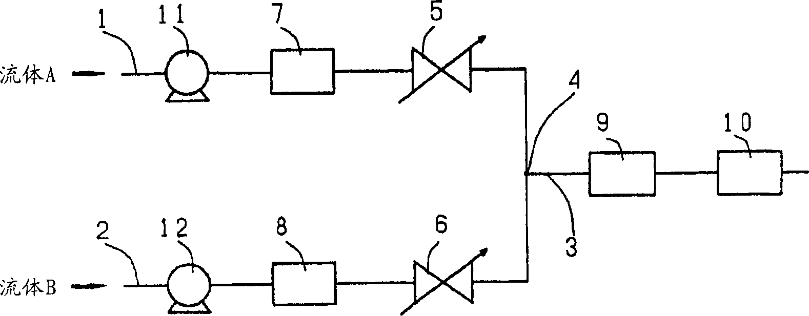
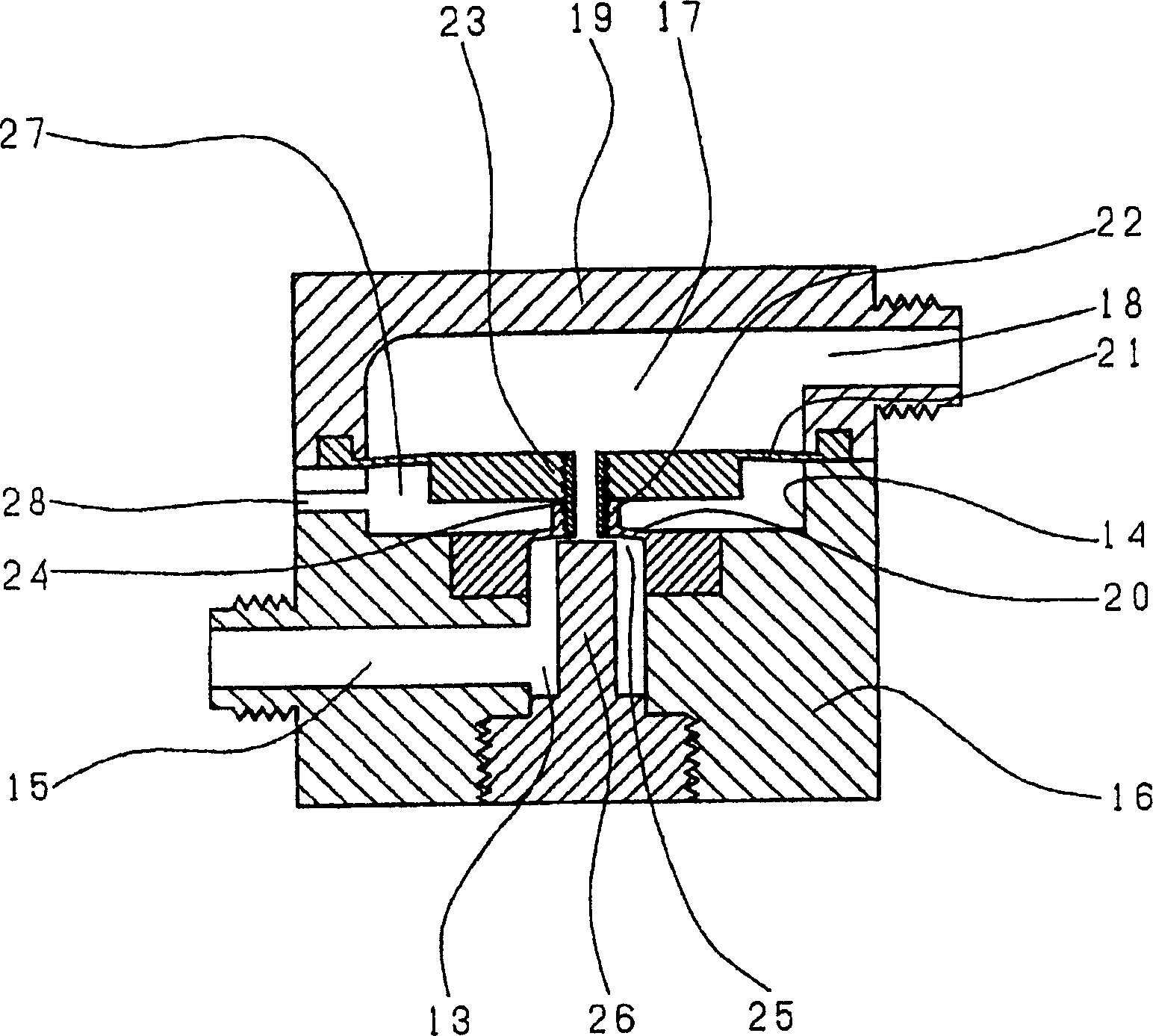
[0019] The first embodiment of the present invention refers to figure 1 , image 3 illustrate. Reference numeral 1 is a first supply line through which fluid A flows, and a pump 11, a pressure reducing valve 7, and a needle valve 5 as a throttling portion are arranged in series from the upstream side; reference numeral 2 is a second supply line through which fluid B flows, Similar to the first supply line 1 , the pump 12 , the pressure reducing valve 8 , and the needle valve 6 as a throttling portion are arranged in series from the upstream side. Reference numeral 4 is a confluence junction in the device, which is a position where the quantitatively supplied fluids A and B merge. Reference numeral 3 is a mixing line, a line on the downstream side below the joining point 4 ...


PUM


Abstract

A fluid mixing device in which even if the pressure on the downstream side of a back pressure valve of a mixing line fluctuates, the fluid in each supply line can always be supplied quantitatively to the mixing line, maintaining a high-precision mixing ratio, and further in making the fluid In the flowing state, the mixing ratio of the fluid supplied to the line can be changed with high precision. On the upstream side of the confluence joint (4) where at least two first supply lines (1), second supply lines (2) and mixing lines (3) meet, throttles (5, 6) for adjusting the flow rate of the fluid and Pressure reducing valves (7, 8) on the upstream side of the throttling parts (5, 6) are arranged in series in the supply lines (1, 2), and a back pressure valve (9) is arranged on the mixing line (3). In addition, the back pressure valve (9) and flow meter (10) are arranged in series on the mixing line (3), the throttling parts (5, 6) use fixed holes or regulating valves, and the pressure reducing valves (7, 8) and the back pressure Pressure valve adopts automatic valve.

Description

technical field [0001] The present invention relates to a fluid mixing device for quantitatively supplying fluid flowing in at least two supply lines to a mixing line in fluid transportation in various industries such as chemical plants or semiconductor manufacturing fields, food fields, and biological fields. Even if the pressure on the downstream side of the back pressure valve of the mixing line fluctuates, the fluid in each supply line can be quantitatively supplied to the mixing line while maintaining a high-precision mixing ratio, and the fluid in the supply line can not be pumped. A fluid mixing device that changes the mixing ratio of the mixing line by controlling it, and can change the mixing ratio of the mixing line while the fluid is flowing by adjusting the flow rate of only one supply line. Background technique [0002] As an example of an existing fluid mixing device such as Figure 7 The fluid mixing device shown (for example, disclosed in JP-A-2000-250634). ...

Claims


Application Information

Patent Timeline
IPC IPC(8): B01F15/00B01F3/08B01F5/00B01F15/02B01F15/04G05D11/02G05D11/03
CPCG05D11/03B01F23/49B01F35/833
Inventor 上村忍文吉野研郎
Owner ASAHI YUKIZAI KOGYO CO LTD
Why Eureka
Try Eureka