Optical image stabilizer for camera lens assembly

An optical image and stabilizer technology, applied in optics, camera, image communication, etc., can solve the problems that hinder the reduction of the size of the camera lens assembly and the installation of the camera lens assembly.

Inactive Publication Date: 2006-05-10
SAMSUNG ELECTRONICS CO LTD
View PDF0 Cites 12 Cited by
  • Summary
  • Abstract
  • Description
  • Claims
  • Application Information

AI Technical Summary

Problems solved by technology

However, due to the two steps on the two surfaces of the image sensor, the conventional image stabilizer hinders the reduction in the size of the camera lens assembly.
Therefore, it is difficult to mount the camera lens assembly on a product that requires a space for mounting additional components, such as a portable terminal

Method used


Image

  • Optical image stabilizer for camera lens assembly
  • Optical image stabilizer for camera lens assembly
  • Optical image stabilizer for camera lens assembly

Examples


Embodiment Construction

[0031] Hereinafter, embodiments of the present invention will be described with reference to the accompanying drawings. For clarity and conciseness, detailed descriptions of well-known functions and constructions are omitted since they would obscure the subject matter of the present invention.

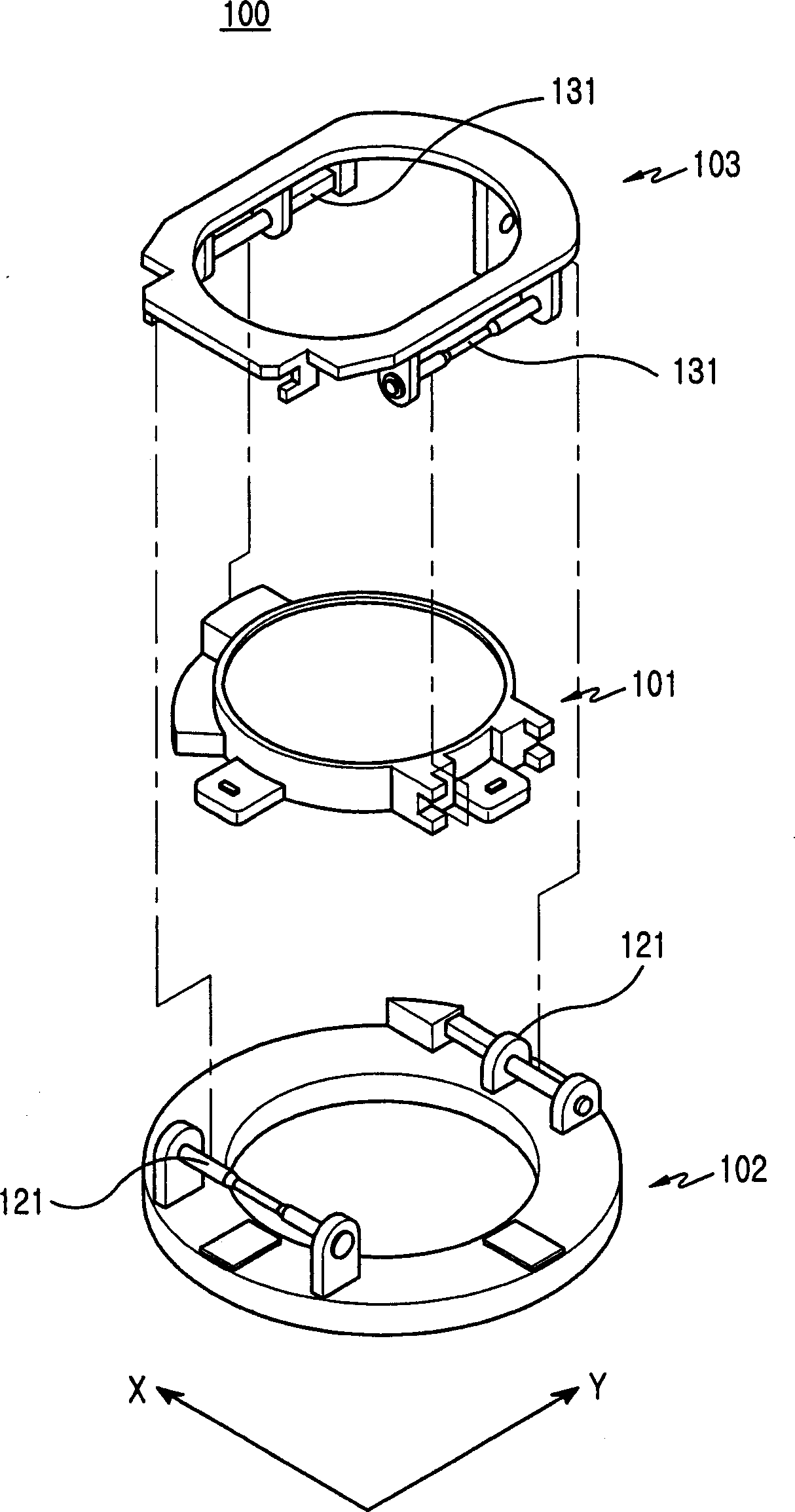
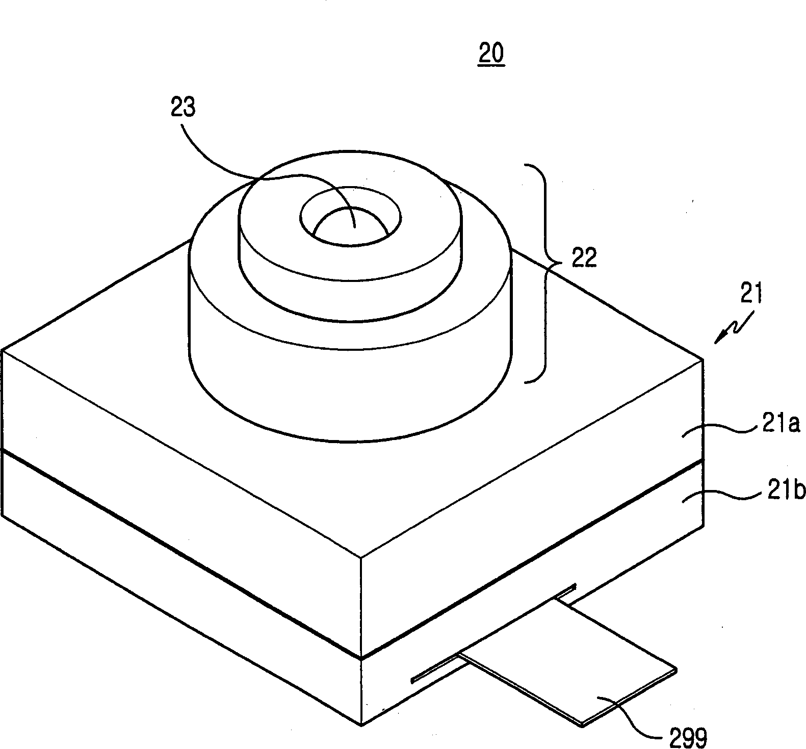
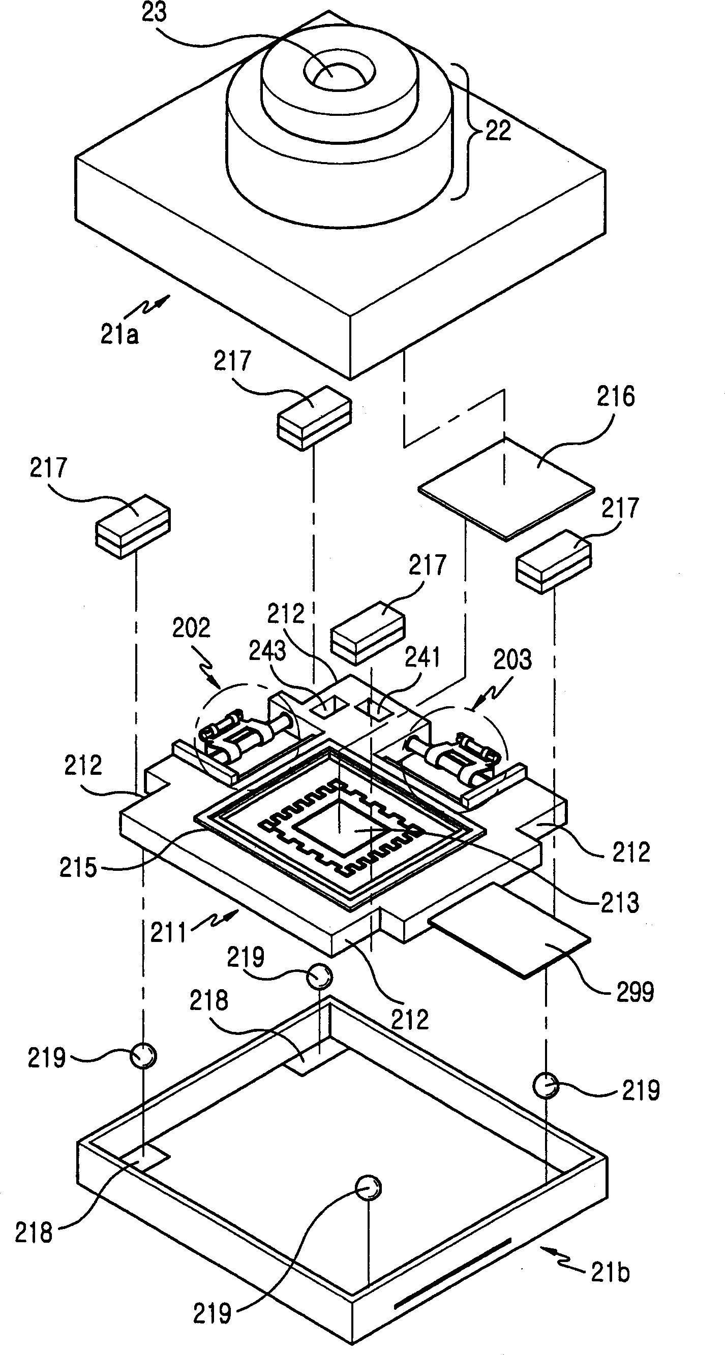
[0032] refer to Figure 2-4 , the optical image stabilizer 200 of the camera lens assembly 20 according to the present invention is provided on the casing 21 , specifically, in the lower casing 21 b of the camera lens assembly 20 . In operation, the optical image stabilizer 200 performs image stabilization by correcting the position of the image sensor 213 according to the shaking of the user's hand.

[0033] The camera lens assembly 20 has a housing 21 including an upper housing 21a and a lower housing 21b, and a light pipe 22 in which at least one lens (not shown) is accommodated. The light pipe 22 extends from the upper housing 21a and has an exposed window 23 on the terminal surf...


PUM


Abstract

An optical image stabilizer for a camera lens assembly, comprising: a housing; a plate having an image sensor on a top surface and movably disposed in the housing, the plate and the housing being separated from each other; at least one magnetic body, provided Between the plate and the housing, a magnetic body provides a magnetic force acting in a direction in which the plate is in close contact with the inner surface of the housing; at least three balls are provided between the plate and the inner surface of the housing for holding a board so that it is separated from the housing; and a driving unit for correcting the position of the image sensor by moving the board according to the shaking level of the user's hand. In an optical image stabilizer for a camera lens assembly, the drive unit for driving the board on which the image sensor is mounted is basically present on the same surface of the board itself. As a result, the optical image stabilizer can reduce the size of the product provided with the image lens assembly and can improve the reliability of the product.

Description

technical field [0001] The present invention relates to a camera device, and more particularly, to an optical image stabilizer for a camera lens assembly. Background technique [0002] As is known in the art, CCD (Charge Coupled Device) sensors and CMOS (Complementary Metal Oxide Semiconductor) sensors are used to photograph both moving and still images. In particular, CCD sensors offer good characteristics in terms of image quality compared to CMOS sensors. However, the CCD sensor has the disadvantage of high power consumption and a complicated structure. As such, the CMOS image sensor has disadvantages of high power consumption and complex structure. Thus, CMOS image sensors are more popular in the market, especially in the field of portable digital devices. [0003] When photographing moving images using an imaging sensor, unstable images are often photographed due to external causes such as shaking of the user's hand and camera shake caused by the camera moving on the...

Claims


Application Information

Patent Timeline
Patent Type & Authority Applications(China)
IPC IPC(8): G03B13/32
CPCH04N23/54H04N23/68H04N23/687H04N23/60
Inventor 辛斗植
Owner SAMSUNG ELECTRONICS CO LTD
Why Eureka
Try Eureka