Driving apparatus

A technology of driving device and driving shaft, which is applied in the direction of transmission device, friction transmission device, electromechanical transmission device, etc., can solve the problems of unfavorable transportation of heavy objects, increase of cost, and limitation of transmission torque, etc., and achieve simple structure, rotation Torque improvement, the effect of increasing the misalignment limit

Inactive Publication Date: 2006-05-10
MARUYASU KIKAI KK
View PDF2 Cites 12 Cited by
  • Summary
  • Abstract
  • Description
  • Claims
  • Application Information

AI Technical Summary

Problems solved by technology

[0005] However, in the driving device shown in Patent Document 1, the driving magnet wheel and the driven magnet wheel intersect each other one-to-one, and power is transmitted from one part of the intersection. There is a limit to the transmission torque of the shaft), which is small
Therefore, the driving device is used for conveying lighter items, etc., which is not conducive to the driving device for conveying heavy objects.
[0006] In the above-mentioned driving device, as a method of increasing the torque or increasing the torque, it can be considered to increase the outer diameter of the driving magnet wheel and the driven magnet wheel, but if the diameter of the driving magnet wheel and the driven magnet wheel is increased, Then, of course, the cost will increase, and the overall size of the driving device will also increase. As a result, there will be a problem that the device using the driving device will also increase in size.

Method used


Image

  • Driving apparatus
  • Driving apparatus
  • Driving apparatus

Examples


Embodiment 1

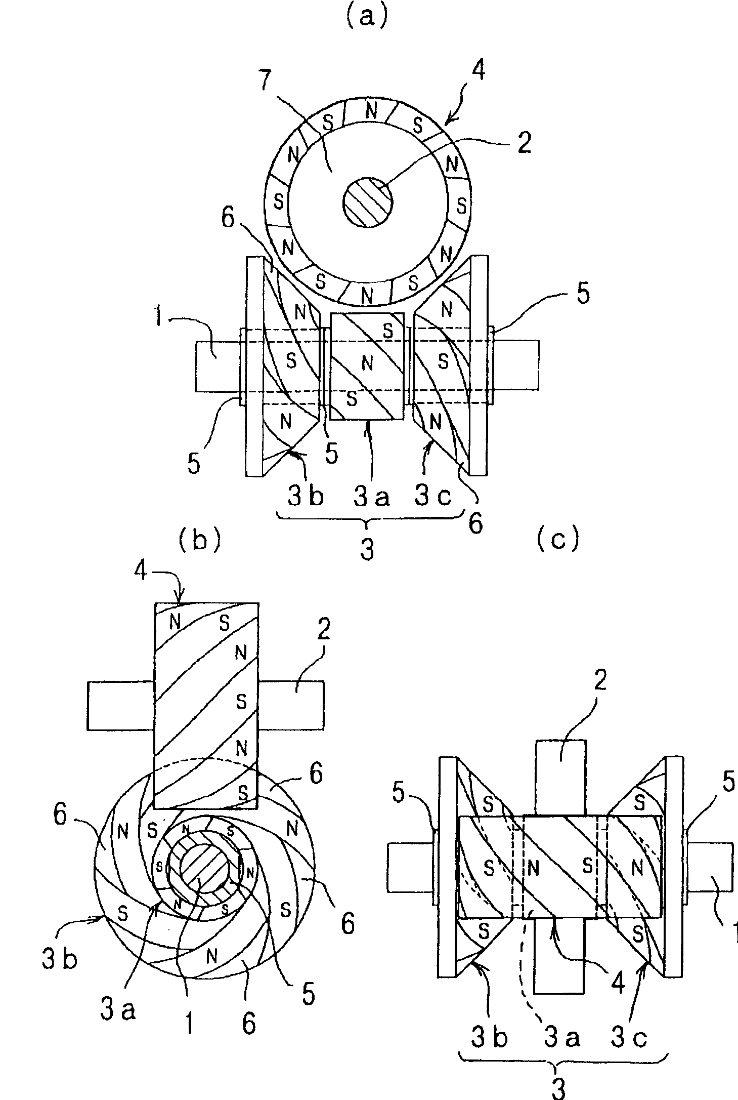
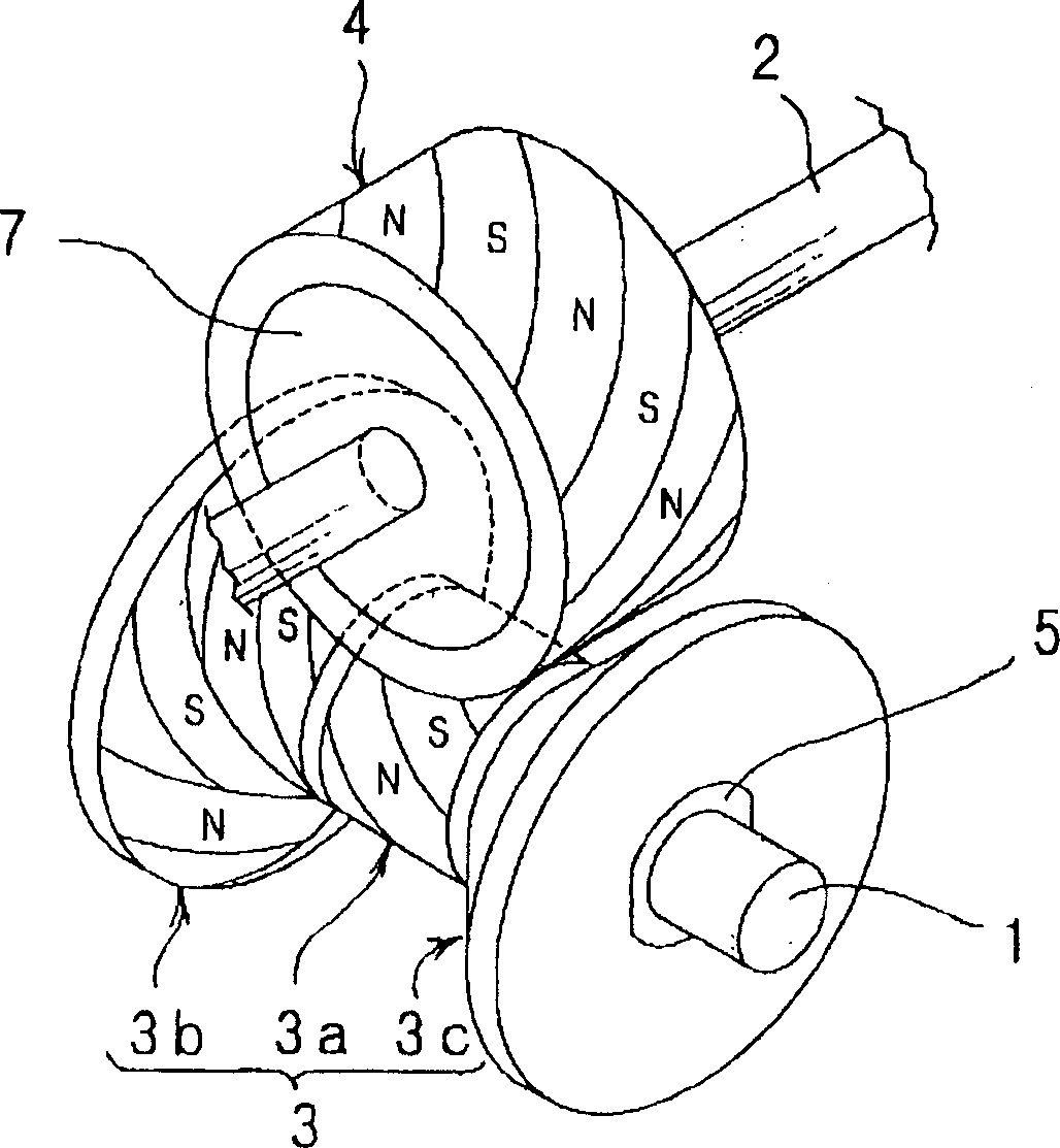
[0041] figure 1 and figure 2The driving device is shown, and the driving device generates magnetic action at three points of the non-contact driving magnetic wheel mounted on the driving shaft with respect to the cylindrical driven magnetic wheel mounted on the driven shaft to perform power transmission, In the figure, symbol 1 is the drive shaft, symbol 2 is the driven shaft arranged at right angles to the above-mentioned drive shaft 1, symbol 3 is the driving magnet wheel fixed on the above-mentioned drive shaft 1, and symbol 4 is fixed on the above-mentioned driven shaft. Driven magnet wheel for axis 2.

[0042] The drive magnet wheel 3 that is fixed on the drive shaft 1 is composed of a cylindrical magnet wheel 3a and frustoconical magnet wheels 3b, 3c arranged on both axial sides of the magnet wheel. The frustoconical magnet wheel 3b and 3c make the truncated conical surface face each other, and are arrange|positioned sandwiching the cylindrical magnet wheel 3a.

[00...

Embodiment 2

[0052] Figure 4 and Figure 5 It is a driving device, which respectively forms the driving magnet wheel 8 fixed on the drive shaft 1 and the driven magnet wheel 9 fixed on the driven shaft 2 into a drum shape, and arranges the two magnetic wheels at right angles in a non-contact state. The concave surface of wheel 8,9.

[0053] The drum-shaped magnetic wheels 8, 9 are the same as the driven magnetic wheel 4 of the above-mentioned embodiment 1, and the cylindrical magnetic wheels 8a, 9a and the truncated conical surfaces arranged oppositely on both sides in the axial direction are formed. Shaped magnetic wheels 8b, 8c, 9b, 9c constitute.

[0054] That is, the driven magnet wheel 4 of the first embodiment described above has the same configuration as the drive magnet wheel 3 of the first embodiment described above, and is arranged to cross at right angles in a non-contact state. In addition, the cylindrical magnet wheels 8a, 9a constituting the drive magnet wheel 8 and the d...

Embodiment 3

[0058] Image 6 and Figure 7 It is a driving device, and the driving device respectively forms the driving magnetic wheel 10 fixed on the driving shaft 1 and the driven magnetic wheel 11 fixed on the driven shaft 2 into a drum shape, and the two magnetic wheels 10, 11 make their truncated conical surfaces A frusto-conical magnet wheel is arranged oppositely on the shaft, and the concave curved surfaces of the drive magnet wheel 10 and the driven magnet wheel 11 are arranged to intersect at right angles in a non-contact state.

[0059] That is, it is a configuration in which the cylindrical magnet wheels 8a, 9a are removed from the configuration of the driving magnet wheel 8 and the driven magnet wheel 9 of the second embodiment described above. In addition, frustoconical magnet wheels 10 a , 10 b , 11 a , 11 b constituting the driving magnet wheel 10 and the driven magnet wheel 11 are respectively formed to have the same diameter.


PUM


Abstract

The present invention provides a driving device using magnetism. The driving device does not increase the diameters of the driving magnetic wheel and the driven magnetic wheel, and does not set another transmission system branched from the driving shaft. On the same axis as the shaft of the moving magnetic wheel, the misalignment limit is increased to realize torque improvement. In the driving device of the present invention, the driven shaft is disposed at right angles to the driven shaft driven by an appropriate driving mechanism, and the power transmission from the driving shaft to the driven shaft is performed by a non-contact power transmission mechanism utilizing magnetic force; wherein, in The driving shaft and the driven shaft are respectively equipped with magnetic wheels that alternately magnetize N poles and S poles in a spiral shape, and magnetic action parts from one magnetic wheel to the other magnetic wheel are provided at multiple positions on the same axis.

Description

technical field [0001] The invention relates to a driving device which utilizes a magnetic wheel to non-contactly transmit a rotary driving force. Background technique [0002] Transmission drive devices using gears as mechanisms for transmitting rotational force are widely used in machine tools and industrial machinery. However, a transmission drive device using gears transmits rotational force by meshing the gears with each other, so there is a risk of damage due to high torque, impact, etc. in addition to tooth surface wear, dust generation, and noise generation. [0003] Therefore, as a solution to the above-mentioned problems of the drive device using gears, a drive device using a magnet wheel that transmits a rotational force in a non-contact state has been proposed. [0004] The driving device using a magnetic wheel is opposite to the driving magnetic wheel that magnetizes the N pole and the S pole in a spiral shape, and makes the axis center of the driven magnetic w...

Claims


Application Information

Patent Timeline
Patent Type & Authority Applications(China)
IPC IPC(8): H02K51/00H02K49/10H02N11/00
CPCH02K49/102F16H13/12
Inventor 依田和卫宫坂哲男
Owner MARUYASU KIKAI KK
Why Eureka
Try Eureka