Organic electroluminescent device

An electroluminescent layer and luminescent technology, applied in the direction of electroluminescent light source, electric light source, light source, etc., can solve problems such as structural limitations

Inactive Publication Date: 2006-05-10
INTELLECTUAL DISCOVERY CO LTD
View PDF0 Cites 3 Cited by
  • Summary
  • Abstract
  • Description
  • Claims
  • Application Information

AI Technical Summary

Problems solved by technology

[0010] Although a method for enhancing the contrast of an organic electroluminescent device having the above-mentioned general structure has been discussed and developed, the technical development for enhancing the contrast is limited due to the structure of the device and the characteristics of the materials used.

Method used


Image

  • Organic electroluminescent device
  • Organic electroluminescent device
  • Organic electroluminescent device

Examples


Embodiment Construction

[0023] Hereinafter, embodiments of the present invention will be specifically described with reference to these drawings.

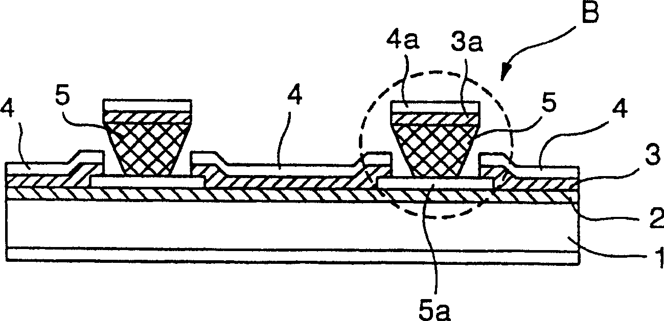
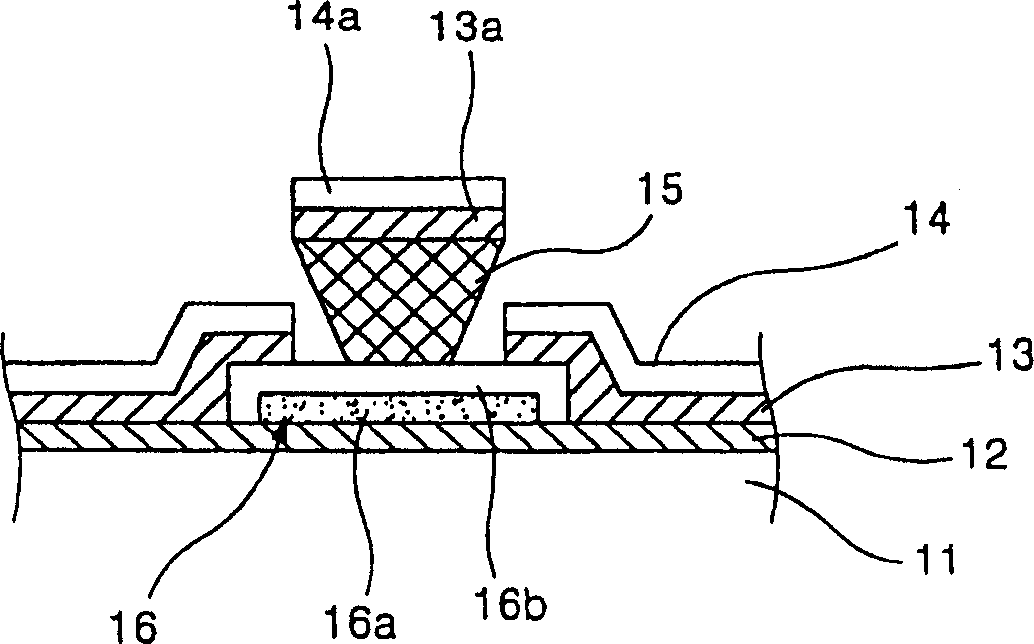
[0024] image 3 is a partial sectional view of the organic electroluminescent device according to the first embodiment of the present invention, which corresponds to figure 2 Part "B" of .

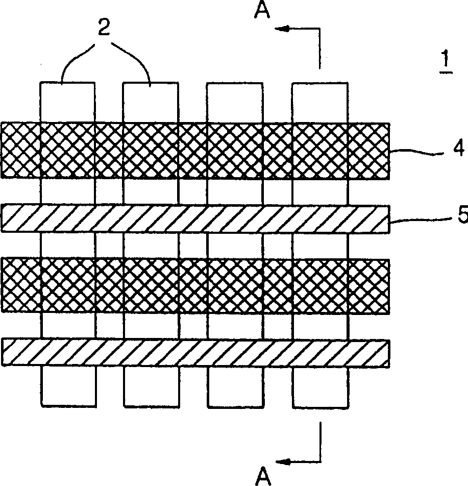
[0025] The whole structure of the organic electroluminescence device in this example is the same as figure 1 and figure 2 as shown. Therefore, only the characteristic part of the organic electroluminescent device in this embodiment is enlarged and shown in image 3 middle.

[0026] Refer below image 3 The procedure for manufacturing the organic electroluminescence device and its structure are described.

[0027] First, an ITO layer 12 is formed on a glass substrate 11 by a vacuum deposition method, and the ITO layer 12 is patterned by a photolithography method to form an ITO electrode. Then, an insulating layer 16 is formed in certain regions of the ITO lay...


PUM


Abstract

The present invention is characterized by having a structure capable of reducing the reflectance of external light when the device is not operating, that is, when the device is not emitting light. To this end, the structural components formed on the non-luminous regions are formed from a dark black matrix material. In order to have such a structure, the present organic electroluminescent device includes an indium tin oxide (ITO) layer formed on a glass substrate; an insulating layer formed on a non-light-emitting region of the ITO layer, each insulating layer being formed of a dark-colored material a plurality of walls formed on the insulating layer; and an organic electroluminescence layer and a metal layer sequentially formed on the entire structure including these walls, the organic electroluminescence layer and the metal layer being connected to the adjacent organic layer through these walls The electroluminescent layer and the metal layer are spaced apart. Each insulating layer is composed of a black matrix film formed on the ITO layer and an insulating film formed on the black matrix film and shaped to cover the black matrix material layer. On the contrary, each insulating layer formed under the wall is composed of an insulating layer formed on the ITO layer and a black matrix film formed on the insulating film. Also, in the present organic electroluminescent device, the walls may be formed with a black matrix material.

Description

technical field [0001] The present invention relates to an organic electroluminescent device, and more particularly, to an organic electroluminescent device whose contrast can be enhanced by forming structural parts on non-light-emitting regions with black matrix materials . Background technique [0002] Organic electroluminescence is a phenomenon in which excitons are formed in a thin film of (low-molecular or high-molecular) organic material by recombination of holes injected from the anode and electrons injected from the cathode, and by The energy produces light of a specific wavelength. [0003] figure 1 is a plan view of an organic electroluminescent device, and figure 2 is along figure 1 Sectional view taken along the midline A-A. These figures schematically show the basic structure of an organic electroluminescent device to which the above-mentioned phenomenon is applied. [0004] The basic structure of an organic electroluminescence device includes a glass sub...

Claims


Application Information

Patent Timeline
IPC IPC(8): H05B33/00H05B33/14
CPCH05B33/22H10K59/173H10K50/865
Inventor 尹明姬
Owner INTELLECTUAL DISCOVERY CO LTD
Why Eureka
Try Eureka