Check patentability & draft patents in minutes with Patsnap Eureka AI!

Recording medium data recording method and device

A technology for data recording and recording media, applied in optical recording/reproducing/erasing methods, optical recording systems, rewriting, etc., which can solve problems such as difficulty in device reproduction, long irradiation time, and inability to form recording marks

Inactive Publication Date: 2006-05-10
PANASONIC CORP
View PDF4 Cites 3 Cited by
  • Summary
  • Abstract
  • Description
  • Claims
  • Application Information

AI Technical Summary

Problems solved by technology

Therefore, in the phase-change recording medium, there is an advantage that it is easy to share the reproducing device with the phase-pit type recording medium, but there is no such deformation in the reproduced signal from the phase-pit type recording medium, so based on the phase-pit type recording medium Reproduction with the same device becomes difficult
[0017] In addition, in the above-mentioned fourth conventional technique, the recording power level of the recording pulse train changes stepwise, so complicated power control is required.
In addition, when recording a signal with a symbol length of 4Tw, light is emitted at a power level higher than the average power level of at least 3Tw, and the density becomes high. Disadvantages of required record marking
[0018] According to the above-mentioned prior arts, marks cannot be formed with sufficient accuracy at high transfer speeds, and as a result, sufficient recording area density and reliability cannot be achieved.

Method used


Image

  • Recording medium data recording method and device
  • Recording medium data recording method and device
  • Recording medium data recording method and device

Examples


Embodiment 1

[0064] First, Embodiment 1 of the data recording device of the present invention will be described.

[0065] In this embodiment, a phase-change type optical disk is used as the recording medium, but the recording medium usable in the present invention is not limited to such an optical disk. For example, a recording medium that can locally form "marks" that have physical properties different from other parts by injecting energy other than light such as magnetic energy and electron beams is suitable for use in the present invention.

[0066] The present invention is characterized by a write strategy capable of controlling the level of energy irradiated to the recording medium (recording energy) with high precision when recording data on the recording medium. Here, the "level of recording energy" means the average energy level of the laser over a period of about 1 / 2 of the detection window width (the change unit of the edge positions of marks and spaces). When a frequency compon...

Embodiment 2

[0117] Refer below Image 6 Embodiment 2 of the data recording method of the present invention will be described.

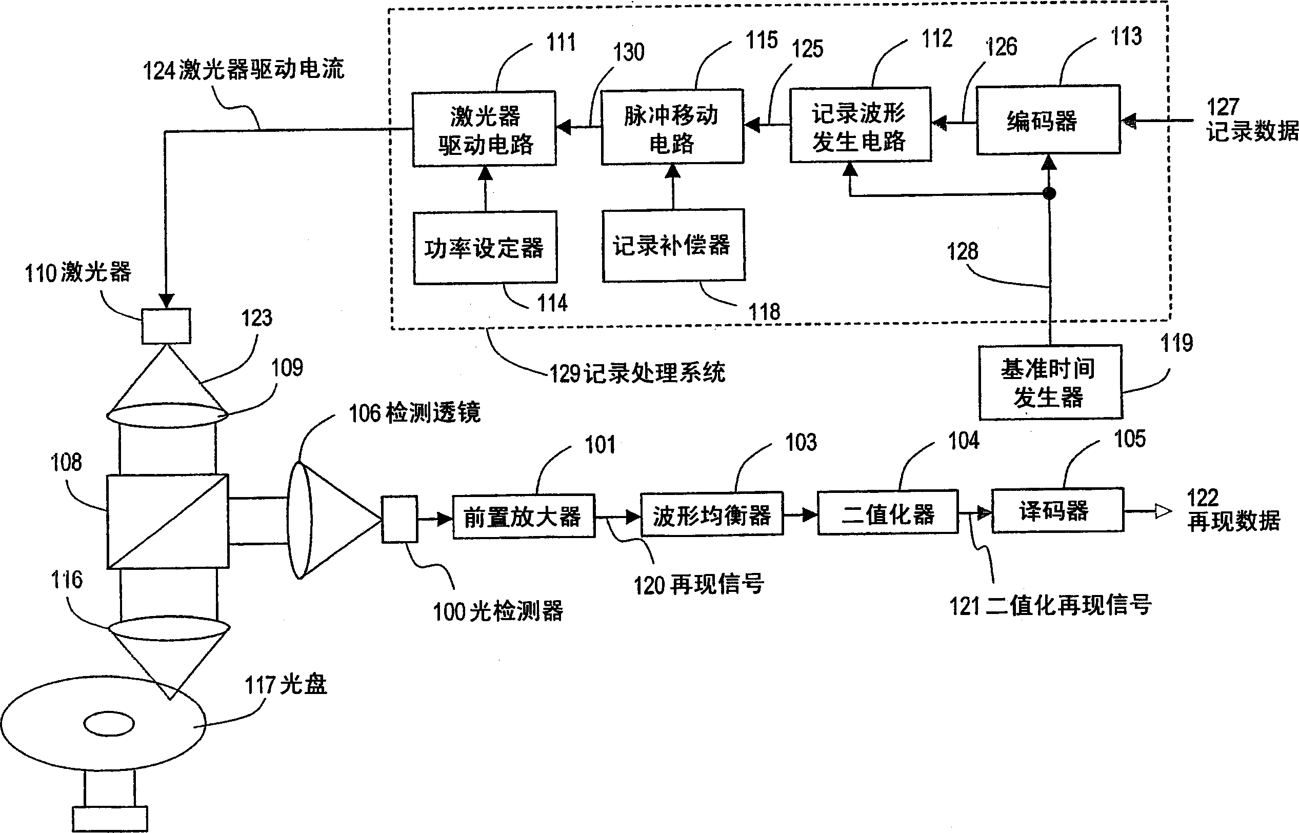
[0118] The data recording method of this embodiment can be executed only by changing the operating program of the data recording device of the first embodiment. Therefore, the structure of the data recording device of this embodiment has the same figure 1 as well as figure 2 The shown structures are substantially the same structure, and detailed description will not be repeated.

[0119] refer to Image 6 (a) to (j) show recording waveforms 600 to 607 of this embodiment.

[0120] by putting Image 6 (a)~(j) and Figure 4 Comparing (a) to (j), it can be seen that the signal waveforms 600 to 607 used in this embodiment are the same as Figure 4 The signal waveforms 400-407 are similar. like Image 6 As shown in (c) to (e), the signal waveforms 600 to 602 are the same as the signal waveforms 400 to 402 . The difference between Embodiment 1 and Embodiment ...

Embodiment 3

[0128] Below, refer to Figure 7 , Embodiment 3 of the data recording method of the present invention will be described.

[0129] The data recording method of this embodiment can be executed only by changing the operating program of the data recording device of the first embodiment. Therefore, the structure of the data recording device of this embodiment has the same figure 1 as well as figure 2 The shown structures are substantially the same structure, and detailed description will not be repeated.

[0130] refer to Figure 7 (a) to (j) show recording waveforms 700 to 707 of this embodiment.

[0131] by putting Figure 7 (a)~(j) and Image 6 Comparing (a) to (j), it can be seen that the signal waveforms 700 to 707 used in this embodiment are the same as Image 6 The signal waveforms 600-607 are similar. The difference between Example 2 and Example 3 is that a period of length 1Tw to 1.5Tw and level Pc is placed at the beginning of the mark non-forming period, and the...


PUM

PropertyMeasurementUnit
wavelengthaaaaaaaaaa

Abstract

Provided is a data recording method, wherein if the shortest code length of the write code sequence is n (which is an integer equal to or greater than one), a write pulse waveform that has only one write pulse is assigned to recording mark making periods corresponding to codes with code lengths x of n, n + 1 and n+ 2, and a write pulse waveform that has multiple write pulses Pw is assigned to recording mark making periods corresponding to codes with code lengths x of n +3 or more. For the symbol with length of n, n + 1, when the number of the write pulse (Pw) contained in the write waveshape during the period of forming the recording mark is equal to the period number of bottom power level (Pb) between two recording pulse (Pw), the pulse width of the symbol length of m (namely the symbol length of m contained in the K-th Pb during the recording mark making period) is less than or equal to that of the symbol length of m + 1 (namely the symbol length of m + 1 contained in the K-th Pb during the recording mark making period), and the recording symbol rank is encoded by 17PP modulation encoding mode.

Description

technical field [0001] The present invention relates to a recording method and apparatus for recording data (information) by irradiating laser light on a recording medium such as an optical disc to form a mark having a physical property different from that of an unrecorded portion. Background technique [0002] A rewritable optical disk such as DVD-RAM has a phase-change recording film provided on a substrate. When the phase-change recording film is irradiated with laser light having a high energy density, the temperature of the irradiated portion locally reaches a temperature exceeding the melting point and melts. Since the optical disc irradiated with laser light rotates at high speed, the beam spot of the laser light moves at high speed along the track on the phase change recording film. Therefore, the portion of the phase-change recording film that was melted by the passage of the beam spot immediately cools naturally and solidifies. By adjusting the power of the laser...

Claims


Application Information

Patent Timeline
Patent Type & Authority Applications(China)
IPC IPC(8): G11B7/0045G11B7/006
Inventor 中村敦史古宫成
Owner PANASONIC CORP
Features
  • R&D
  • Intellectual Property
  • Life Sciences
  • Materials
  • Tech Scout
  • Unparalleled Data Quality
  • Higher Quality Content
  • 60% Fewer Hallucinations
Learn More