Sealed, thermally insulated tank incorporated into the load-bearing structure of a ship

A technology for load-bearing components and thermal insulation, applied in the direction of hull parts, hulls, hull panels, etc., can solve problems such as a large number of assembly steps

Active Publication Date: 2006-05-17
GAZTRANSPORT & TECHNIGAZ
View PDF2 Cites 30 Cited by
  • Summary
  • Abstract
  • Description
  • Claims
  • Application Information

AI Technical Summary

Problems solved by technology

Although the result is a good compromise of buckling strength and thermal insulation, it has

Method used


Image

  • Sealed, thermally insulated tank incorporated into the load-bearing structure of a ship
  • Sealed, thermally insulated tank incorporated into the load-bearing structure of a ship
  • Sealed, thermally insulated tank incorporated into the load-bearing structure of a ship

Examples


Embodiment Construction

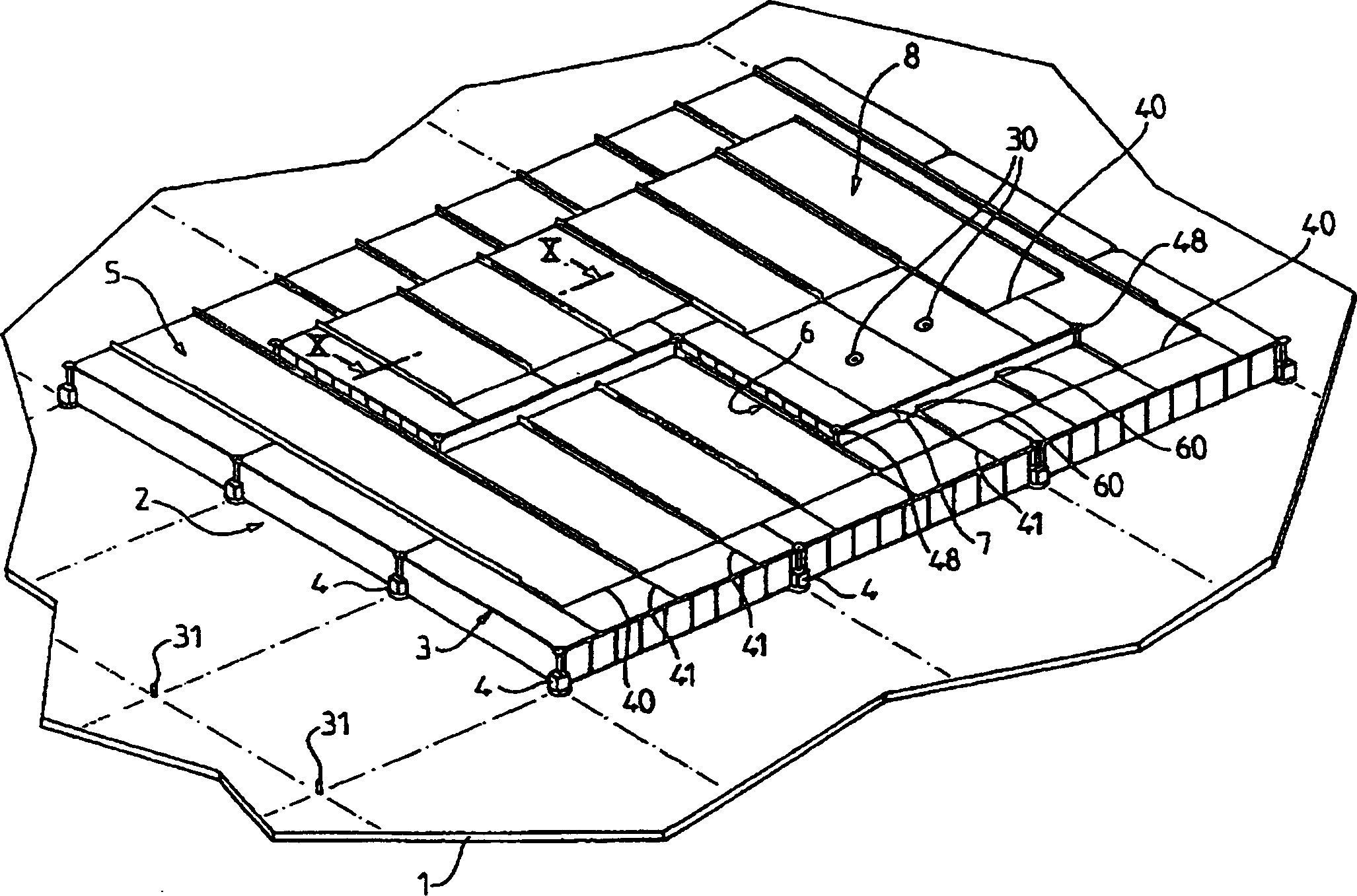
[0059]A description is given below of several embodiments of a hermetically insulated tank comprising and secured to the double hull of a component of a FPSO or FSRU type carrier or a methane carrier. The overall structure of such tanks is known per se and has a polyhedral shape. Therefore, only a description is given of the wall area of ​​the tank, it being understood that all walls of the tank have a similar structure.

[0060] now refer to Figures 1 to 12 A description is given of an embodiment. figure 1 Denotes an area of ​​the double hull of a ship marked with 1. The tank wall comprises in sequence along its thickness a second insulating barrier 2 formed by a watertight box 3 juxtaposed on the double hull 1 and fastened thereto by means of second fixings 4 , then by the waterproofing The second airtight partition 5 carried by the box 3, then the main thermal insulation partition 6 formed by the juxtaposed waterproof box 7 fixed on the second airtight partition 5 by me...


PUM


Abstract

A sealed and insulated tank comprising a tank wall fixed to a load-bearing member of a ship, said tank wall having a main sealing compartment, a main insulating compartment, a second Two airtight barriers and a second thermally insulating barrier, at least one of said thermally insulating barriers consisting essentially of juxtaposed thermally non-conductive components (3), each thermally non-conductive component comprising a thermally insulating liner, at least one plate and passing through said thermally insulating The thickness of the liner is raised to withstand the pressure of the load-bearing partition. These partitions include at least one buckling-resistant partition (14) comprising a plurality of buckling-resistant wall members having buckling-resistant wall members each forming an angle with respect to the general longitudinal direction of the buckling-resistant partition. Orientation, such as corrugations or double-walled sections.

Description

field of invention [0001] The present invention relates to the manufacture of hermetically sealed and insulated tanks comprising tank walls secured to load-bearing members of a floating structure suitable for the manufacture, storage, loading, shipping and / or unloading of cooling liquids such as liquefied gases, Especially those liquefied gases with high methane content. The invention also relates to a methane carrier provided with such a tank. Background technique [0002] Sea transport of liquefied gases at relatively low temperatures involves preferably as small a daily voyage evaporation rate as possible, which means that the thermal insulation of the tanks concerned should be increased. [0003] There has been proposed a hermetically insulated tank comprising a tank wall fastened to a load-bearing member of a ship, said tank wall having primary hermetic compartments sequentially along the thickness direction from the inside of said tank to its outside , a main insulat...

Claims


Application Information

Patent Timeline
IPC IPC(8): B63B3/68B63B25/16F17C3/02
CPCB63B25/16F17C3/027F17C2201/0157F17C2201/052F17C2203/0325F17C2203/0329F17C2203/0333F17C2203/0341F17C2203/035F17C2203/0354F17C2203/0358F17C2203/0631F17C2203/0651F17C2209/227F17C2221/033F17C2223/0161F17C2223/033F17C2270/0107F17C2270/0113F17C2270/0123Y10S220/901B63B3/68
Inventor J·德莱姆P·米沙尔斯基V·法尔冈
Owner GAZTRANSPORT & TECHNIGAZ
Why Eureka
Try Eureka