
Non-classified end cone insulation for catalytic converter

a technology of end cone insulation and catalytic converter, which is applied in the direction of machine/engine, lighting and heating apparatus, separation processes, etc., can solve the problems of reducing the insulation property of heat shields or insulation, reducing the insulation property, and not always practicable or feasible to locate such items. , to achieve the effect of good insulating properties, low cost and good resistance to vibration

Active Publication Date: 2007-03-22
3M INNOVATIVE PROPERTIES CO
View PDF15 Cites 59 Cited by
  • Summary
  • Abstract
  • Description
  • Claims
  • Application Information

AI Technical Summary

Benefits of technology

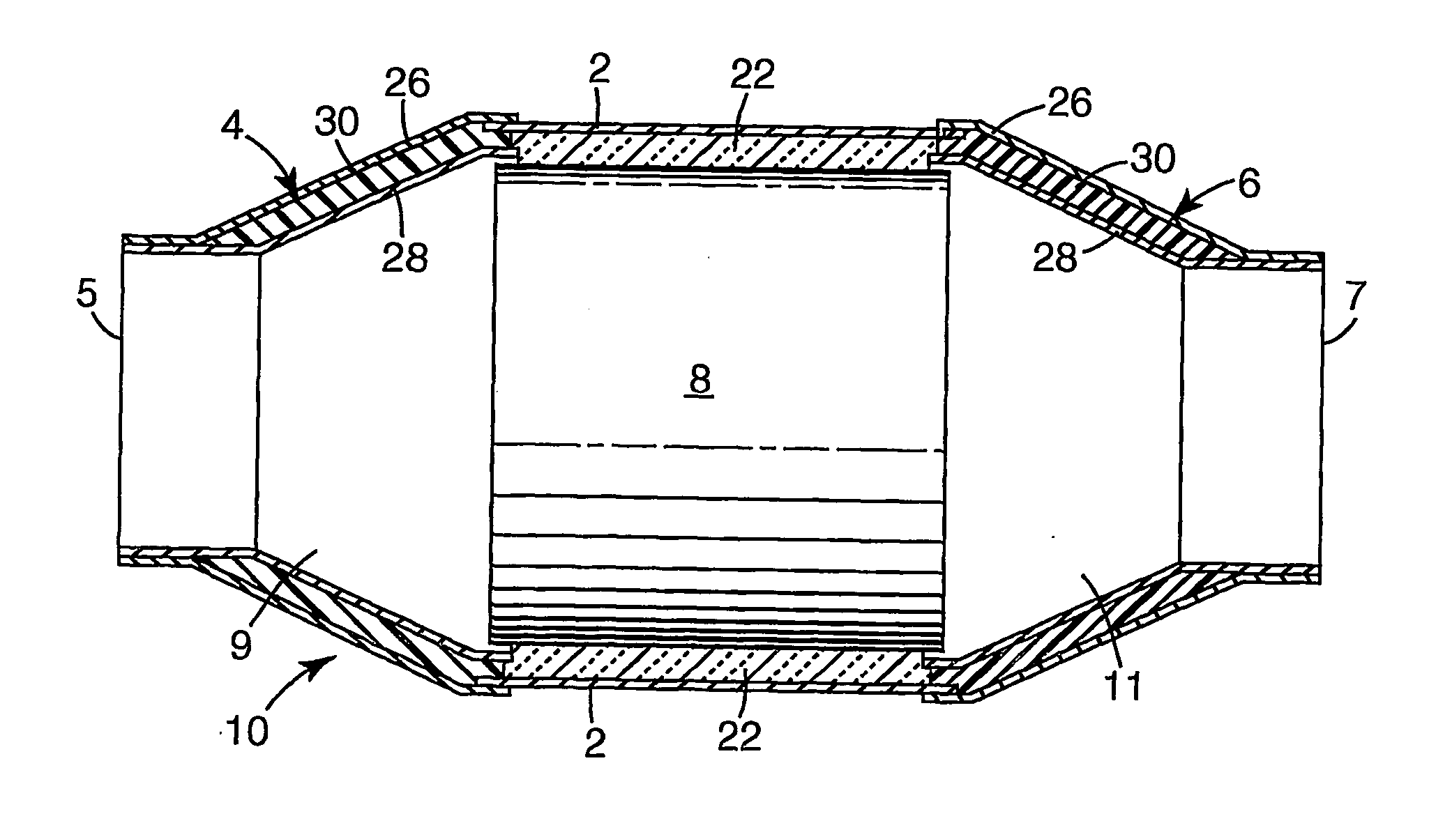
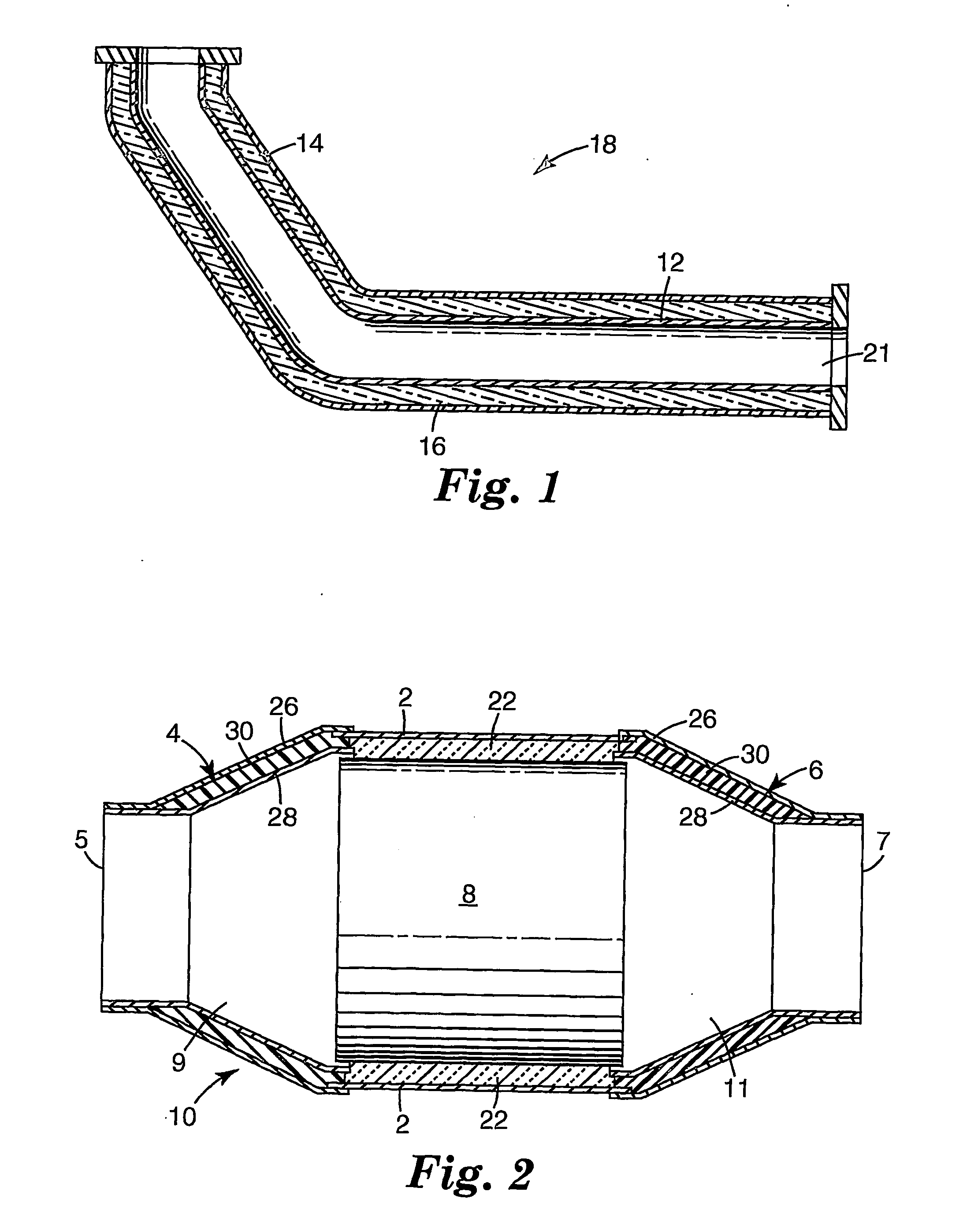
[0012] It was found that an insulation material made of chopped aluminium silicate glass fibers offers good insulating properties when used in the gap of a double wall of an exhaust system component. Further, such insulation material can be manufactured in an easy and convenient way and at a low cost. Also, the insulation material generally provides good resistance to vibrations occurring while in use in a motor vehicle. The insulation material can further be readily designed for use with high temperature exhaust such as from a gasoline engine as well as for low temperature exhaust such as for example from diesel engines, in particular turbo diesel engines.

Problems solved by technology

Heat shields or insulation can be costly when the item to be protected is large, such as a plastic gasoline tank, and it is not always feasible or practical to locate such items away from the exhaust system.
However, in application, the large vermiculite particles can vibrate relative to the mat forming holes in the mat, reducing its insulation property and in a worst case eventually leading to the destruction of the mat.
Particles or pieces of mat escaping from the cone area can lead to plugging of the monolith cells, which in turn can lead to extremely high backpressure and failure of the catalytic converter.
Amorphous, refractory, ceramic fiber mats were also tried as insulation material for end cone regions of catalytic converters, but these mats generally lacked sufficient resiliency to provide long term durability as an end cone insulation.
In addition, they also suffer from destruction of the mat upon vibrations typically encountered in motor vehicles.
But even then the vibration resistance is still not satisfactory.
Moreover, the annealing step adds further manufacturing steps making manufacturing less convenient and adding costs.
These fibers generally perform well as insulative material in exhaust system components but they are much more expensive than the materials referred to above making their use in exhaust system components generally unattractive.

Method used


Image

  • Non-classified end cone insulation for catalytic converter
  • Non-classified end cone insulation for catalytic converter

Examples


example 1

[0069] R-glass fibers (60% SiO2, 25% Al2O3, 9% CaO, and 6% MgO) having a diameter of ca. 10 μm, chopped to a length of 36 mm, obtained from Saint-Gobain Vetrotex, were processed into a web by the following method. The glass fibers were opened in a two-zone Laroche opener. The first zone had a feed speed of 2 m / min and a Lickerin roll speed of 2,500 rev / min. The second zone had a feed speed of 4 m / min and a Lickerin roll speed of 2,500 rev / min. The output speed was 6.5 rn / min.

[0070] The opened fibers were then fed into a conventional web-forming machine (commercially available under the trade designation “Rando Webber” from Rando Machine Corp. of Macedon, N.Y., wherein the fibers were blown onto a porous metal roll to form a continuous web. The continuous web was then needle-bonded on a conventional needle tacker. The needle speed was 100 cycles / min and the output speed was 1.1 m / min. The “weight per area” of the mat could be adjusted as desired.

[0071] The mat of Example 1 was subj...

example 2

[0073] A mat comprising only S-2 glass fibers was prepared by the same method as employed in Example 1. This mat was subjected to RCFT. Results are summarized in Table 3. The mat retained a pressure of at least 17 kPa during the three temperature cycles indicating that sufficient pressure was present to hold the material within the end cone.

example 3

[0074] A two-layer mat was prepared by laminating two separately prepared layers together. The first layer comprised R-glass. The second layer comprised E-glass. Each of the layers was prepared by the method described in Example 1. The two layers were put together by needle-bonding. The mounting mat formed in this manner had two discrete layers of glass of differing compositions. The composition of the two-layer mat of Example 3 is summarized in Table 1.

[0075] The two layer mat of Example 3 was subjected to the RCFT with the S-glass layer positioned towards the hotter of the two platens in the RCFT. The mat retained a pressure of at least 5 kPa during the three temperature cycles indicating that sufficient pressure was present to hold the material within the end cone.


PUM

PropertyMeasurementUnit
Percent by massaaaaaaaaaa

Abstract

An exhaust system component (18, 10) for use in an exhaust system of a motor vehicle. The exhaust system component comprises a double wall surrounding a space (9, 11; 21) through which exhaust gas may flow when the exhaust system component is in use in an exhaust system. The double wall is comprised of a first and second metal wall (12, 14; 26, 28) that define between them a gap. The gap comprises an insulation material (16) made of chopped aluminium or magnesium aluminium silicate glass fibers. The insulation material can be in the form of, for example, an end cone perform. The exhaust system component can be an exhaust pipe (18).

Description

1. FIELD OF THE INVENTION [0001] The present invention relates to an exhaust system component for use in an exhaust system of a motor vehicle, in particular a motor vehicle having an internal combustion engine. The invention relates in particular to an insulation material for use in the gap of a double wall of the exhaust system component. The invention further relates to an exhaust system of a motor vehicle and to an end cone preform of insulation material. 2. BACKGROUND OF THE INVENTION [0002] With the advent of more and more plastic and electronic components on motorized vehicles, particularly automobiles, it is becoming more important to insulate these items from the hot components of the exhaust system. Presently, individual components or specific areas of the car are protected by heat shields or insulation, or are located a sufficient distance from the exhaust system to avoid heat. Heat shields or insulation can be costly when the item to be protected is large, such as a plast...

Claims


Application Information

Patent Timeline
IPC IPC(8): B01D53/34B01D50/00F01N3/10F01N13/08F01N13/14F01N13/16
CPCC03C3/083C03C3/085C03C3/087C03C3/091Y10T29/49345F01N13/14F01N2310/02Y10T29/49398F01N3/10Y02A50/20F01N3/28
Inventor MERRY, RICHARD P.
Owner 3M INNOVATIVE PROPERTIES CO
Learn More