Rolling piston capable of changing sliding friction to rolling friction between piston and cylinder
A rolling piston and sliding friction technology, applied in the direction of piston, cylindrical piston, plunger, etc., can solve the problems of troublesome replacement of piston rings and cylinder liners, easy wear, and reduced efficiency, so as to reduce mechanical wear, prolong service life, The effect of reducing friction
- Summary
- Abstract
- Description
- Claims
- Application Information
AI Technical Summary
Problems solved by technology
Method used
Image

Examples
Embodiment Construction
[0016] The implementation of the present invention will be described in detail below in conjunction with the accompanying drawings, but they do not constitute a limitation to the present invention.
[0017] A method for changing sliding friction between a piston and a cylinder into rolling friction is realized by rolling marbles or rollers on the cylinder wall.
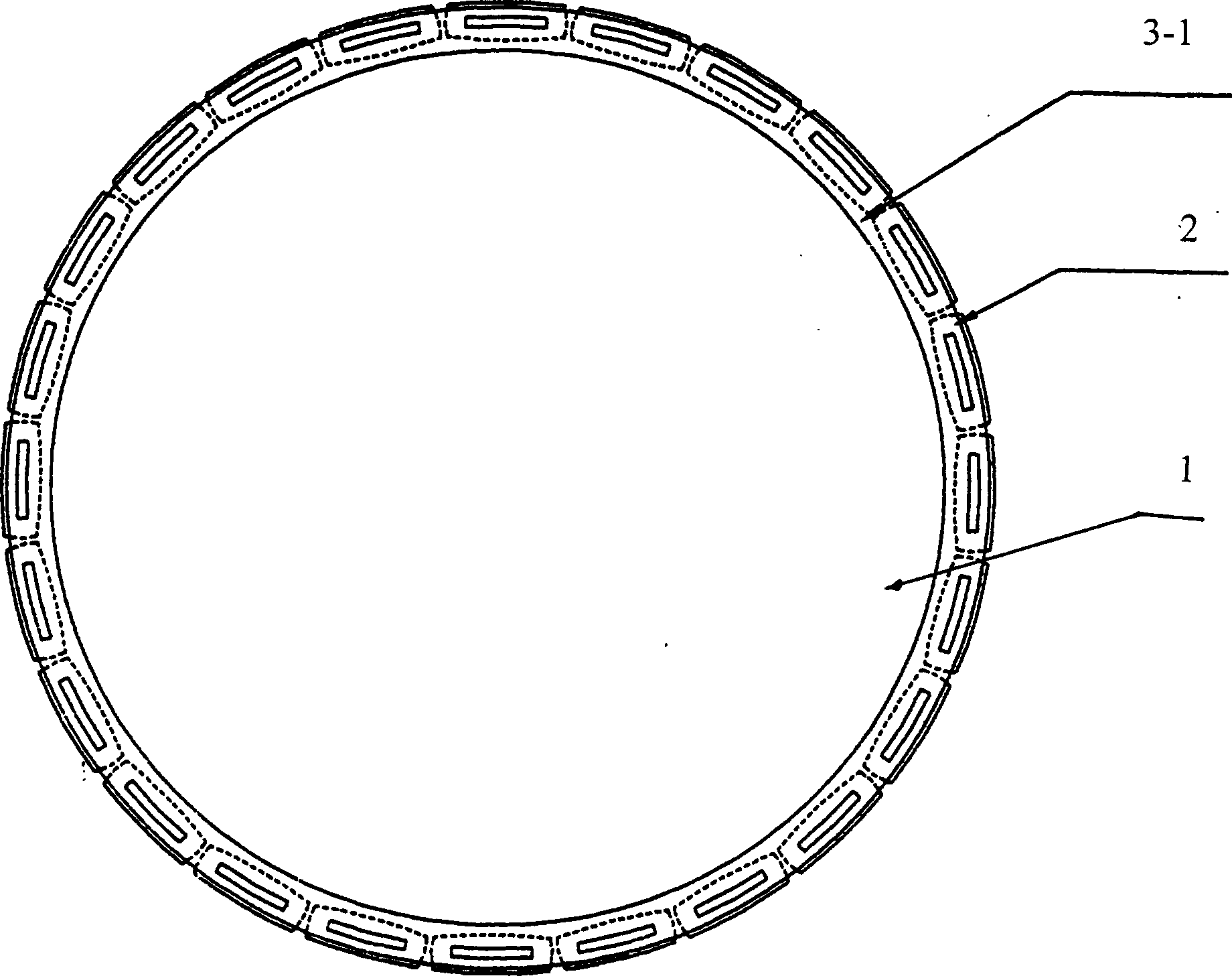
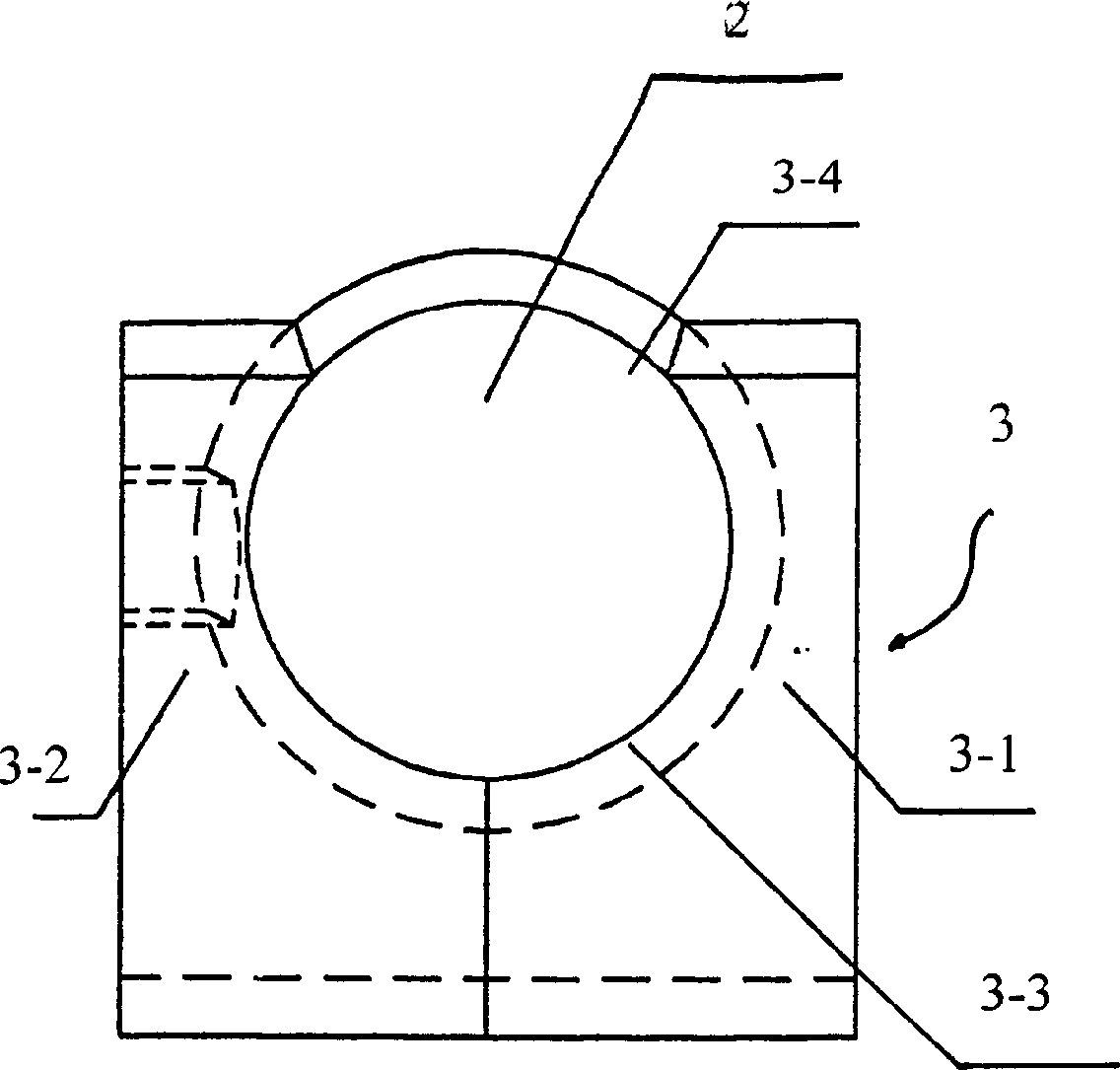
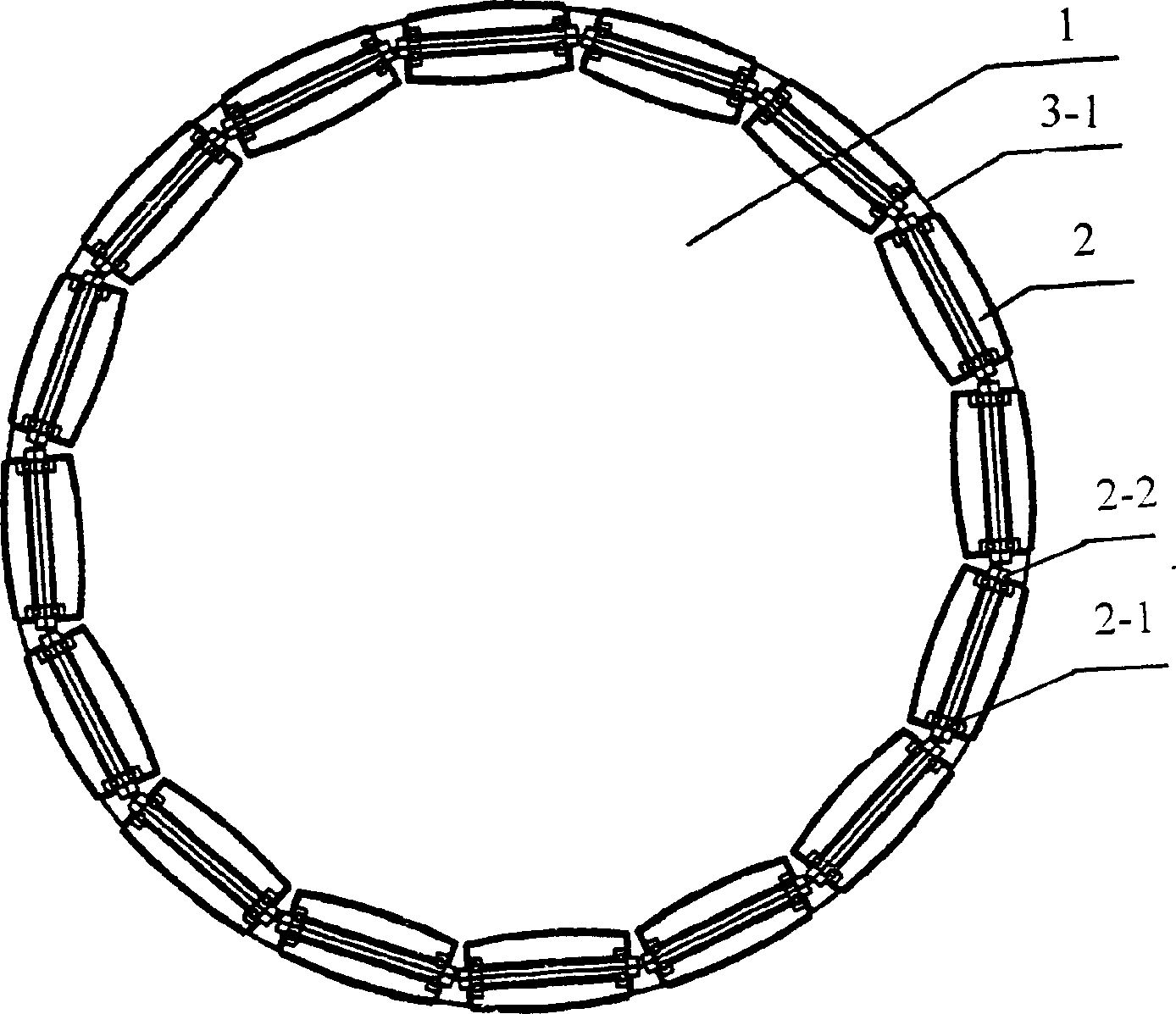
[0018] refer to figure 1 , figure 2 It can be seen that one embodiment of the present invention is composed of a piston body 1 and several rolling elements 2 located around the piston body, and there is a connecting fixture 3 between the piston body and the rolling elements.
[0019] The rolling body 2 is a roller, the connecting fixture includes an upper piston sleeve 3-1 and a lower piston sleeve 3-2, and the roller 2 is located between the upper piston sleeve 3-1 and the lower piston sleeve 3-2 In the groove 3-3, and partially located outside the opening 3-4 between the upper piston sleeve and the lower piston s...
PUM
 Abstract
Description
Claims
Application Information
PatSnap Eureka turns technology decisions into work you can execute. Powered by our Innovation Knowledge Graph, it runs expert workflows across engineering, life sciences, materials and intellectual property. Get your review-ready output in minutes.


