
Miniature sprayer sealing device

A sealing device and sprayer technology, applied in the directions of spraying device, liquid spraying device, liquid distribution, etc., can solve the problems of non-sealing, user inconvenience, liquid leakage, etc.

Inactive Publication Date: 2006-05-24
黄建壮
View PDF0 Cites 21 Cited by
  • Summary
  • Abstract
  • Description
  • Claims
  • Application Information

AI Technical Summary

Problems solved by technology

At the same time, due to the inertia effect caused by the vibration, the valve stem drives the head cap to move up and down to produce an unsealed state. The liquid passes through the air hole and flows out from the gap, resulting in liquid leakage. cause a lot of inconvenience

Method used


Image

  • Miniature sprayer sealing device
  • Miniature sprayer sealing device
  • Miniature sprayer sealing device

Examples


Embodiment Construction

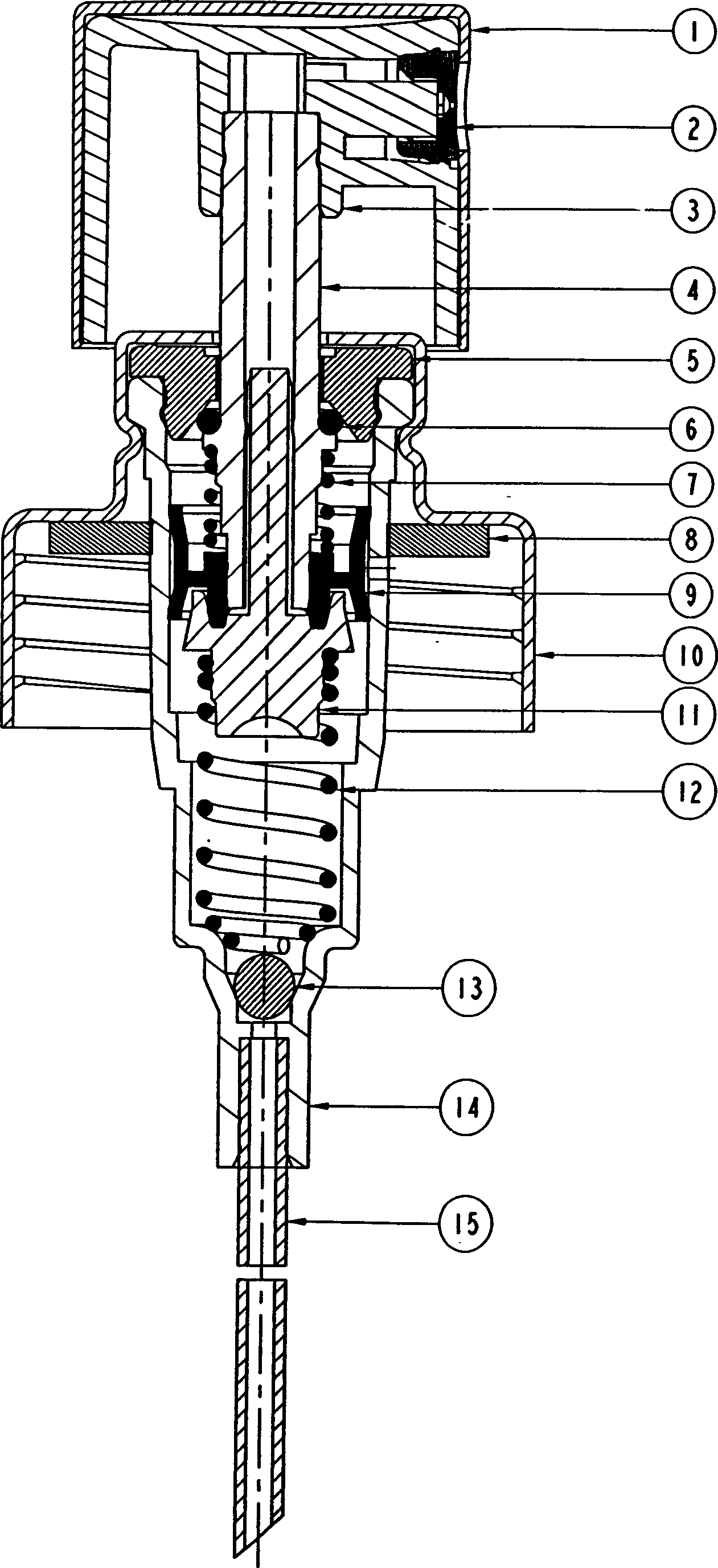
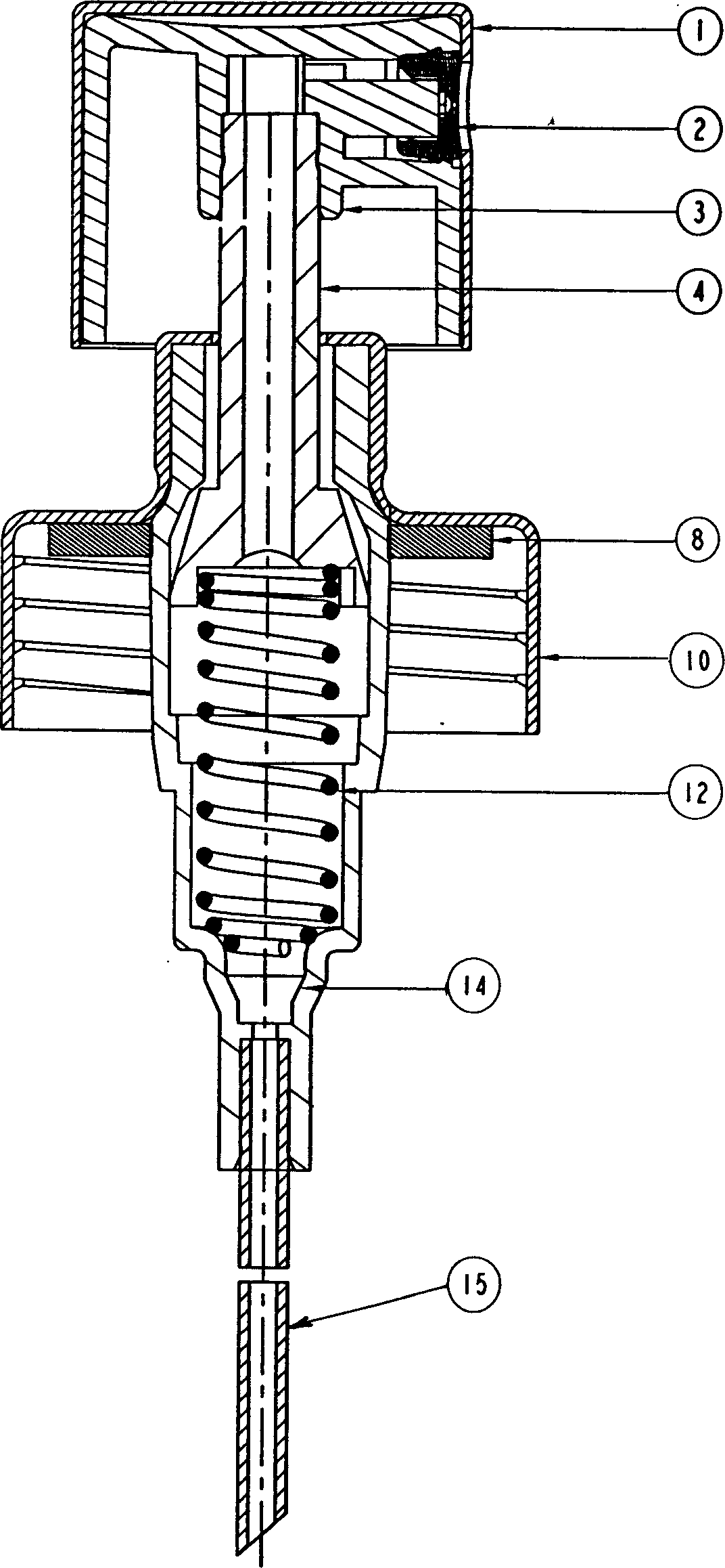
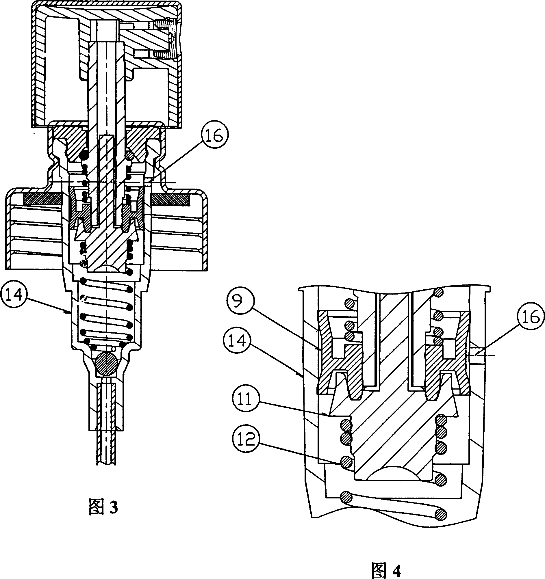
[0026] The implementation mode takes the working principle of the present invention as an example. When put into practice, the pump body 14 is placed in the liquid bottle (the drawing of the liquid bottle is omitted in the accompanying drawings), and the thread of the bayonet 10 is screwed tightly with the screw of the bottle neck. When the lower pressure head presses the cap 1, the valve stem 4 drives the whole system to move downward. At this time, the internal pressure of the pump body 14 increases continuously. When the pressure is greater than the pressure of the short spring 7 on the piston 9, the seal between the piston 9 and the valve needle 11 Disconnected at B. The short spring 7 is sleeved on the valve stem 4, with one end against the step surface of the valve stem 4 and one end against the end face of the piston 9. The pressure increases the sealing of the joint between the piston 9 and the valve needle 11. The liquid at h inside the pump body 14 flows into the v...


PUM


Abstract

The present invention relates to a miniature sprayer sealing device designed for preventing leakage. Said device includes the following several components: push-cap, spraying piece, head cap, valve rod, sealing ring, fastener, long spring, pump body and suction tube. Said invention also provides the concrete structure of every above-mentioned component, connection mode of all the components and working principle of said miniature sprayer sealing device.

Description

technical field [0001] The invention relates to the field of micro-sprayers, and relates to a device for preventing liquid leakage of the sprayer. Background technique [0002] As we all know, the micro-sprayer is different from the vacuum pump. During the working process, the micro-sprayer uses its own vent hole to keep the pressure inside and outside the container in a balanced state. The liquid filled in the bottle utilizes its structure and sealing performance, and every up and down movement makes a certain pressure inside, otherwise people will not spray mist liquid when pressing. The known similar product is a single-spring pump body, which is widely used in the packaging of spray gel water. The main defects of this product are small spray volume, short spray distance, and requirements for the concentration of the sprayed liquid; at present, perfume sprayers or Cleaning liquid sprayers can achieve their respective functions and purposes, but the products are prone to ...

Claims


Application Information

Patent Timeline
IPC IPC(8): B05B9/04B65D83/14
Inventor 黄建艺
Owner 黄建壮
Learn More