Automatic feeding device for lathe

An automatic feeding and lathe technology, which is applied in the direction of automatic/semi-automatic lathes, turning equipment, tool holder accessories, etc., can solve the problems of not being able to meet the needs of processing small shaft parts, slow feeding speed, etc., to improve the degree of automation and production High efficiency, high feeding efficiency and good feeding stability

Inactive Publication Date: 2006-05-24
宁波市江北西西五金电子有限公司
View PDF0 Cites 24 Cited by
  • Summary
  • Abstract
  • Description
  • Claims
  • Application Information

AI Technical Summary

Problems solved by technology

[0003] The purpose of the present invention is to overcome the slow feeding speed of the existing rotary manipulator feeding device, or use other manipulators to feed materials

Method used


Image

  • Automatic feeding device for lathe
  • Automatic feeding device for lathe
  • Automatic feeding device for lathe

Examples


Embodiment Construction

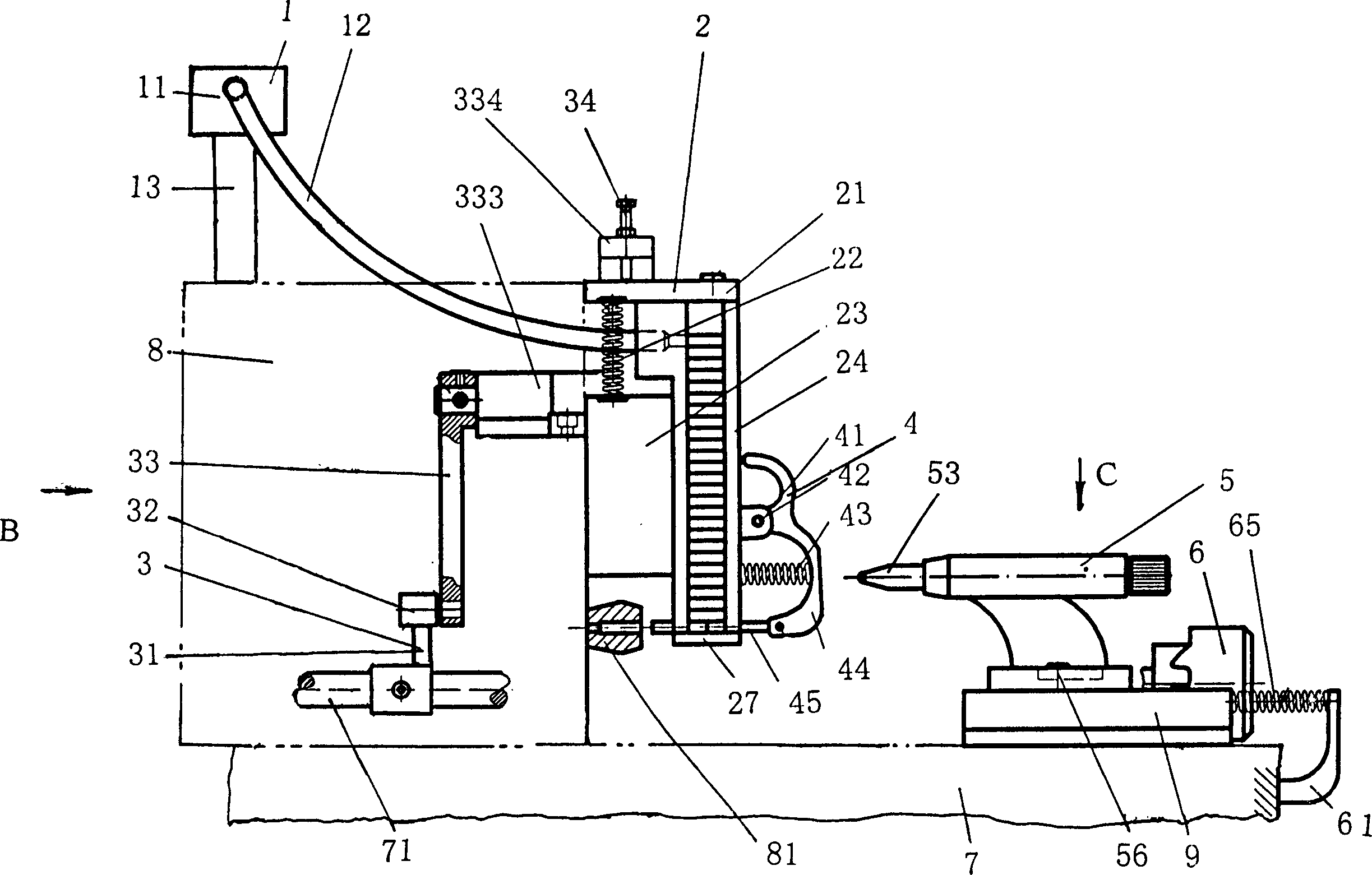
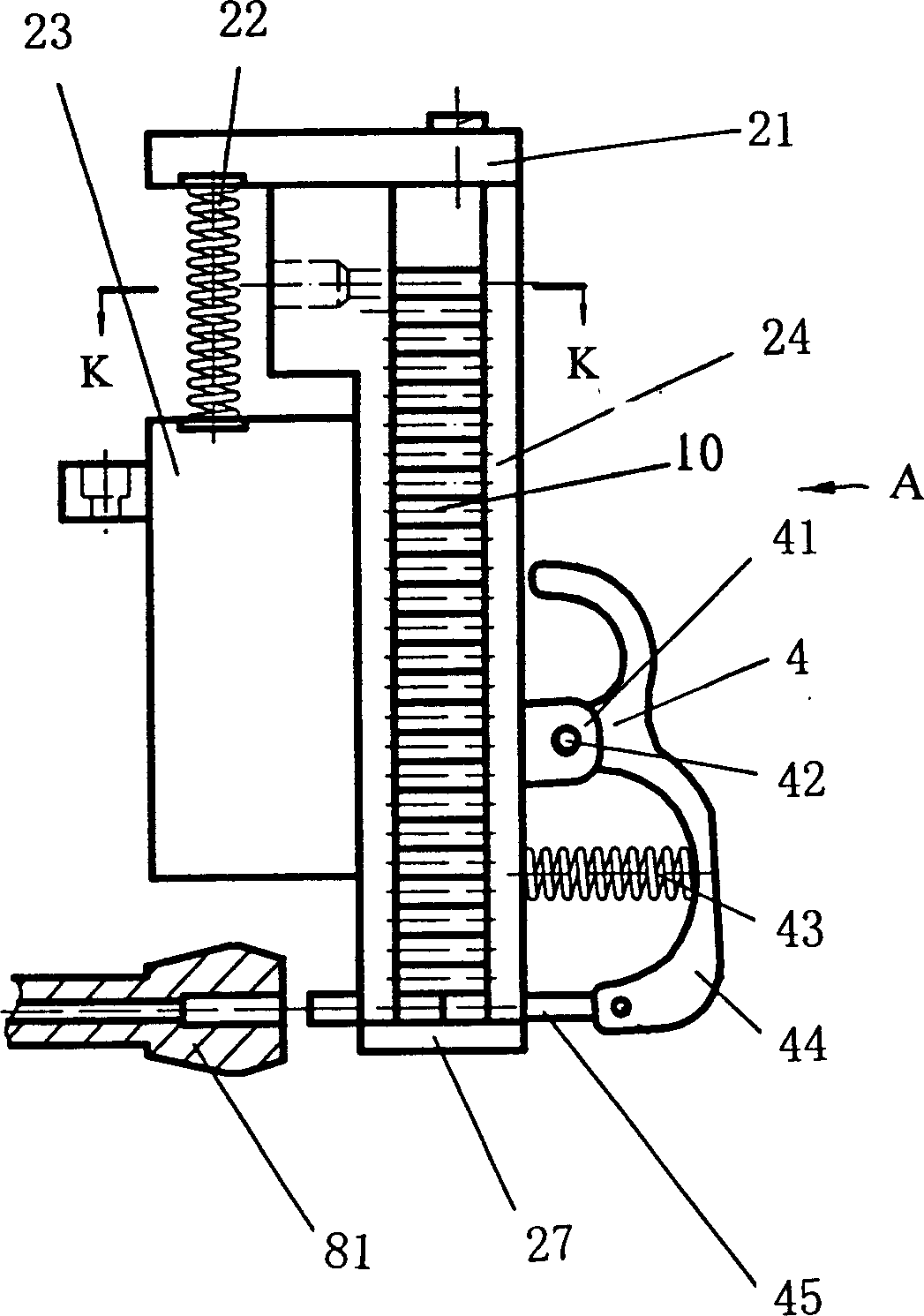
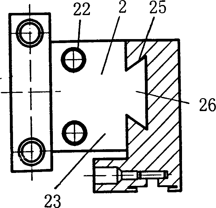
[0019] An embodiment of the present invention will be described below in conjunction with the accompanying drawings. It is composed of discharge part 1, storage bin part 2, transmission part 3, jacking part 4, jacking punch part 5, and transmission part 6. The discharge part 1 is above the bedside box 8 of the lathe, and consists of The material guide pipe 12 of the material part 1 is connected with the storage bin part 2, and the storage bin part 2 is positioned above the main shaft of the bedside box 8, and its bottom plate 23 is fixed on the upper cover plate of the bedside box 8, and the transmission part 3 is formed by a lathe The upper transmission mechanism controls the action, the transmission part 3 controls the workpiece 10 to be processed in the storage bin part 2 to fall in turn, and is placed at the collet 81 on the main shaft sent into the bedside box 8, and then installed on the rear carriage 9 The transmission member 6 on the lathe makes it move through the tra...


PUM


Abstract

The present invention relates to an automatic feeding device for lathe. It is formed from workpiece distributing component, storage bin component, driving component, ejector component and ejection punch component. Said invention also provides concrete mounting method of every component and connection mode of all the components, and can implement quick, stable and high-effective automatic feeding operation.

Description

technical field [0001] The invention relates to a feeding device on a lathe, in particular to an automatic feeding device for a lathe provided with a movable storage bin. Background technique [0002] When machining shaft parts on a lathe, most of the bars are installed in the spindle shaft hole of the bed head box. The cam of the lathe controls the axial movement of the bar, and the chuck on the spindle changes from loosening to clamping the bar. The tool is processed into shape, and then cut by the cutter to complete the processing of one end of the workpiece, and then restart the processing of the next workpiece according to the above sequence. This processing method is easy to cause loss of bar material during cutting. In order to reduce material loss, some small shaft parts are cut according to the required length first, placed in the hopper and automatically fed by a rotary manipulator device; It is also put into the hopper. This kind of material is fed by a rotary m...

Claims


Application Information

Patent Timeline
IPC IPC(8): B23B13/00
Inventor 夏建民王校存
Owner 宁波市江北西西五金电子有限公司
Why Eureka
Try Eureka