

Semi-submersible full-interpass man-vehicle separate flyover
A semi-submersible technology for intercommunication between people and vehicles, applied in roads, roads, buildings and other directions, it can solve the problems of large amount of engineering, aggravated urban pollution, mixed traffic between people and vehicles, etc., to reduce construction costs, maintain urban style, and reduce height. Effect
- Summary
- Abstract
- Description
- Claims
- Application Information
AI Technical Summary
Problems solved by technology
Method used
Image

Examples
Embodiment Construction
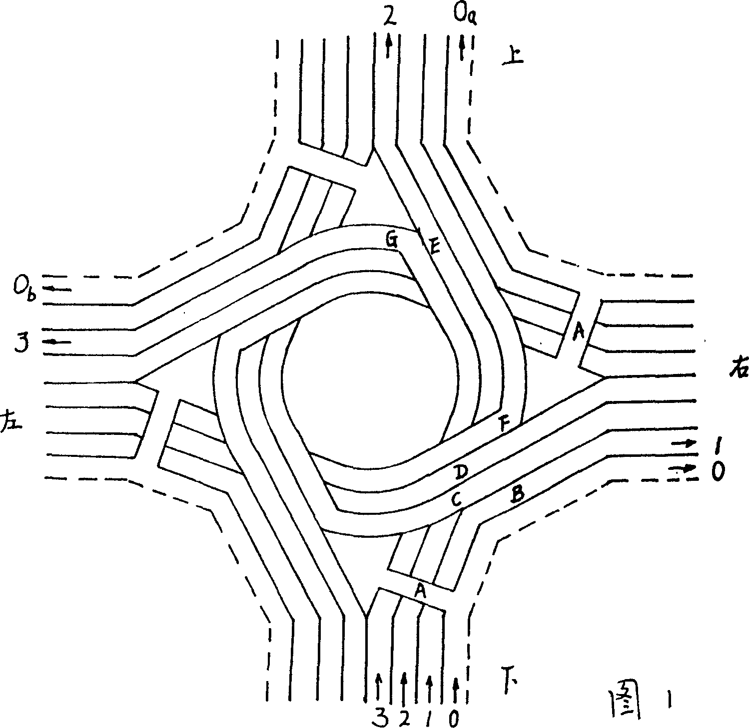
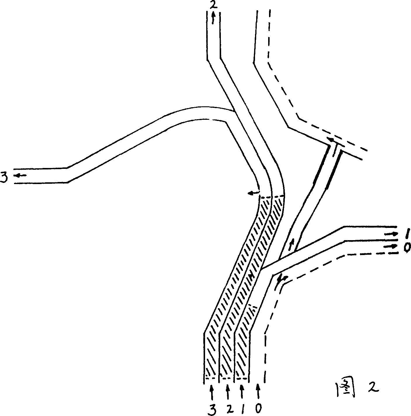
[0012] As shown in Figures 1 and 2: the lower part of the motorway is the base point: ① Turn right: Entrance of Lane 1—pass over the overpass A—upper overpass B—exit of lane 1; or entrance of lane 1—pass over the overpass Bridge A, C, D—overpass B---exit of lane 1; it can also be the entrance of lane 1—overpass B---exit of lane 1. ②Go straight: Entrance of Lane 2----cross overpass A, C, D-up overpass E----Exit of Lane 2; ③Turn left, entrance of Lane 3---cross overpass A, C, D, F-----Upper overpass G-----Exit of Lane 3.
[0013] The following parts of non-motorized vehicle lanes and sidewalks are used as the base point: ①Turn right, entrance of Road 0—exit of Road 0; ②Go straight, entrance of Road 0—cross overpass B, C, D—upward flyover A—exit of Road 0a. ③Turn left, entrance of Road 0—cross overpasses B, C, D—on overpasses A—(go straight from right to left in the same direction as ② method)—exit 0b.
[0014] The traffic with the left, the upper, and the right as base points ...
PUM
 Abstract
Description
Claims
Application Information