Main engine axis positioning method and measuring device

A technology for positioning measurement and positioning tooling, which is applied in the direction of measuring devices, optical devices, instruments, etc., can solve the problem that the measurement of coaxiality cannot be completed, and achieve the effect of improving the quality of the whole machine and accurate positioning

Active Publication Date: 2006-05-24
中国船舶集团渤海造船有限公司
View PDF0 Cites 20 Cited by
  • Summary
  • Abstract
  • Description
  • Claims
  • Application Information

AI Technical Summary

Problems solved by technology

Since the optical path of the axis of the host cannot pass through, it is impossible to measure the coaxiality with the usual optical method, especially a new method is needed to solve this problem

Method used


Image

  • Main engine axis positioning method and measuring device
  • Main engine axis positioning method and measuring device
  • Main engine axis positioning method and measuring device

Examples


Embodiment Construction

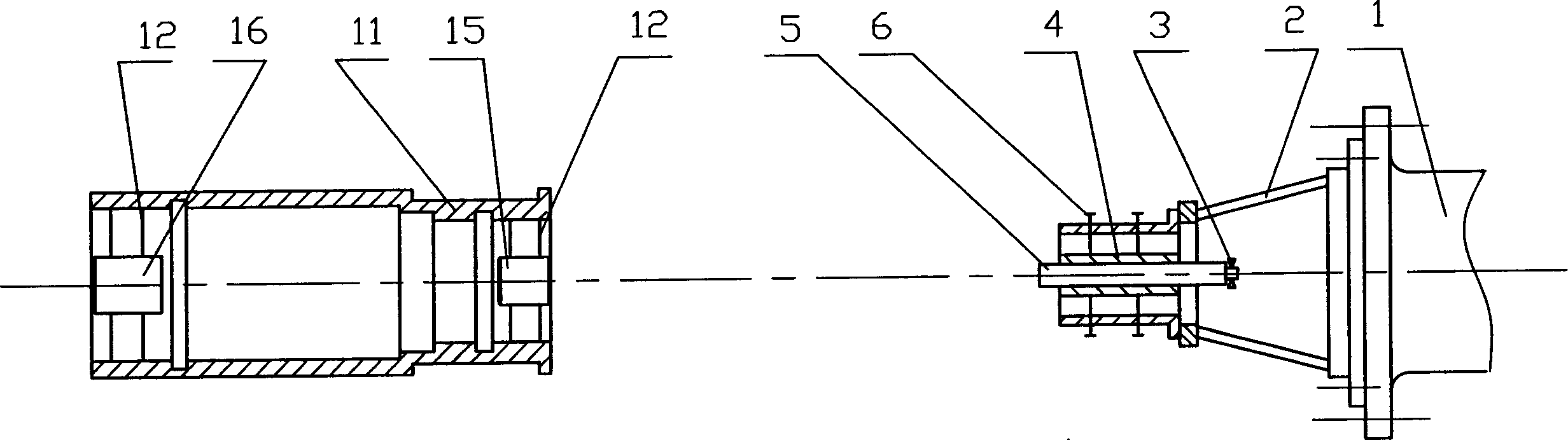
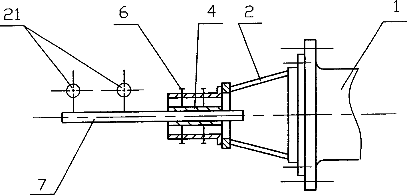
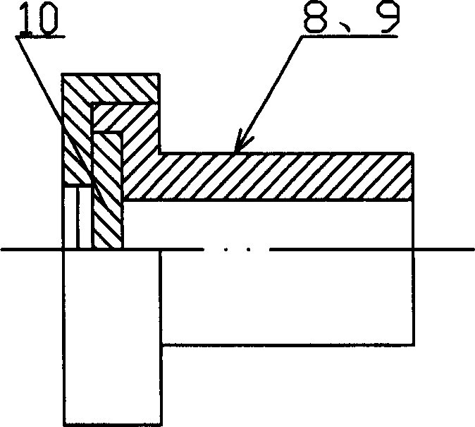
[0022] The axis positioning method and measuring device of the main machine are to realize the axis positioning of the main machine by adopting the micrometer collimation telescope and its accessories and the measuring device arranged along the optical path set therewith. The described micro-collimation telescope accessory includes Φ57.14mm, height 20mm, optical target sheet 10 and right-angle eyepiece 3 of precision 2 ". The host axis positioning measurement device includes two light targets for making and placing the optical target sheet 10. , 9, two light pipes 15 and 16 for setting up light targets 8 and 9, four light target supports 12 for setting up light pipes, the special-purpose internal micrometer positioning shaft 17 that cooperates with light pipes 15 and 16, and the main engine axis positioning tooling 2, Sleeve 4 and the false axis 7 matched with it. Utilize the micrometer collimation telescope, calibrate the light targets 8 and 9 with the optical target sheet 10 ...


PUM


Abstract

The invention includes autocollimator with micrometer, and measuring device. Axis positioning tool set up in the measuring device is installed on output shaft of main machine. The tool set up possesses a sleeve with inner diameter being equal to external diameter of the autocollimator. Dummy spindle is such prepared that its external diameter is equal to the external diameter of the autocollimator. The dummy spindle is put into the sleeve. Using hand turning makes coaxial between the dummy spindle and the main machine. Then, the autocollimator is put into the sleeve after the dummy spindle is pulled out. Thus, it is coaxial between the autocollimator and the main machine. Light pipes including light target are installed on hole of tail shaft at front and back positions. Using the hole of tail shaft as reference makes two light targets coaxial with hole of tail shaft. Using autocollimator adjusts main machine to be coaxial with hole of tail shaft. Features are: accurate positioning.

Description

(1) Technical field [0001] The invention relates to a spatial axis positioning measurement, in particular to a ship main engine axis positioning method and a measuring device. (2) Background technology [0002] The ship's main engine system is the ship's power plant and the heart of the ship, so the positioning and installation of the main engine is very important. During the positioning and installation of the main engine, the shaft hole of the stern shaft has been processed and connected with the hull as a whole. The installation of the main engine requires that the axis of the main engine is coaxial with the center line of the processed stern shaft hole. Since the optical path of the axis of the host cannot pass through, it is impossible to measure the coaxiality with the usual optical method, and a new method is especially needed to solve this problem. (3) Contents of the invention [0003] The technical problem to be solved by the present invention is to provide a ho...

Claims


Application Information

Patent Timeline
Patent Type & Authority Applications(China)
IPC IPC(8): G01B11/27
Inventor 徐斌刘强孙建利姜勇解明贺林华山姜辉马艳张秋惠刘昆
Owner 中国船舶集团渤海造船有限公司
Why Eureka
Try Eureka