Plunger-type master cylinder

A plunger type, master cylinder technology, applied in the direction of hydraulic brake transmission, etc., can solve problems such as damage to the durability of the sealing ring, and achieve the effect of achieving the sealing durability

Inactive Publication Date: 2006-05-24
BOSCH CORP
View PDF4 Cites 10 Cited by
  • Summary
  • Abstract
  • Description
  • Claims
  • Application Information

AI Technical Summary

Problems solved by technology

As a result, a problem arises that impairs the durability of the seal ring

Method used


Image

  • Plunger-type master cylinder
  • Plunger-type master cylinder
  • Plunger-type master cylinder

Examples


Embodiment Construction

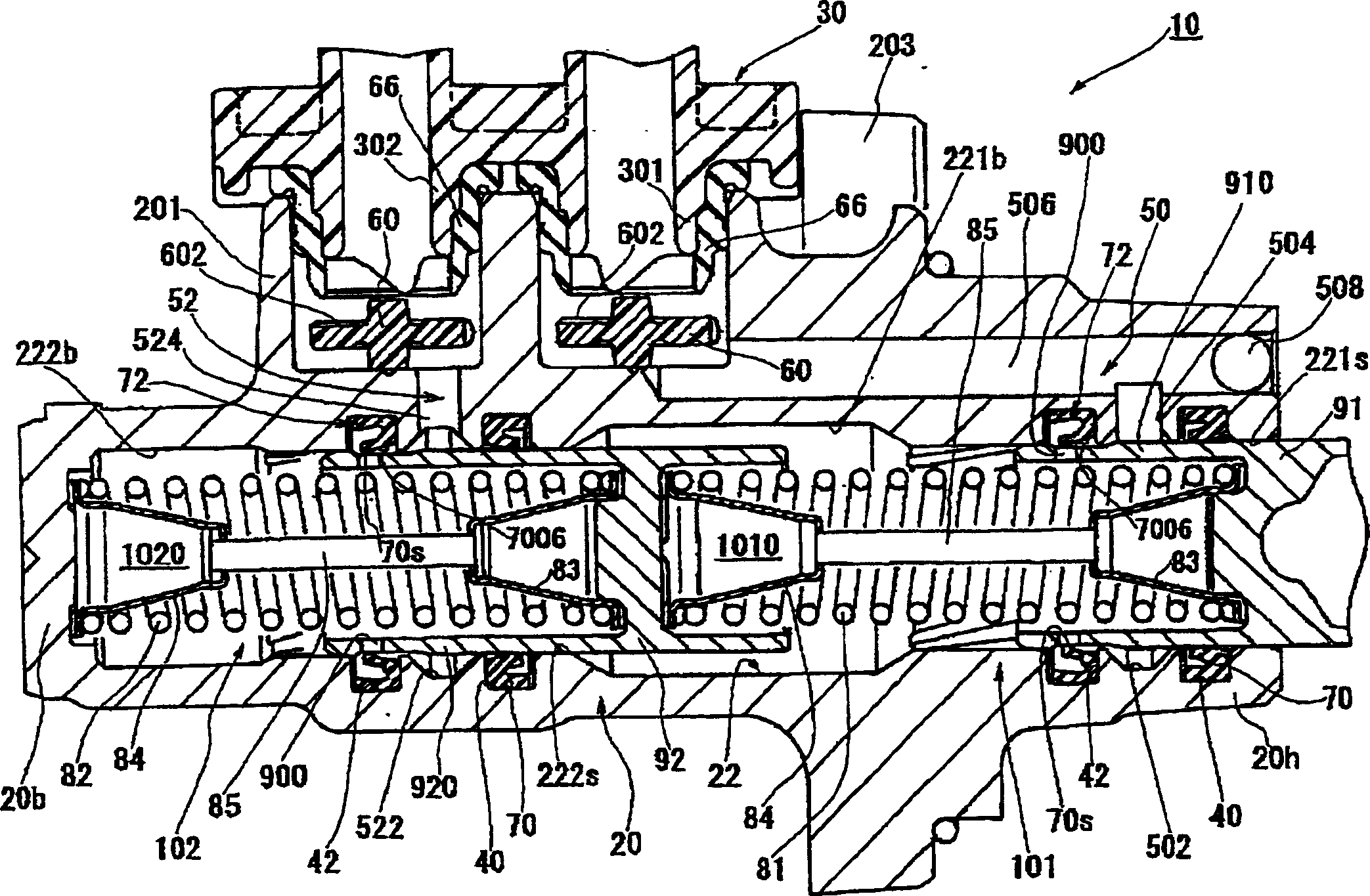
[0033] figure 1 It is an embodiment of the tandem plunger type master cylinder adopting the present invention. The tandem master cylinder 10 has a main part 101 and an auxiliary part 102 that are independent of each other. In the illustrated embodiment, the two parts 101 and 102 adopt the scheme considered in the present invention.

[0034] First, refer to figure 1 The overall configuration of the tandem master cylinder 10 will be described. The shell of the master cylinder 10 is a cylinder block 20 made of aluminum alloy. The upper part of the cylinder 20 is provided with a boss portion 201 for supporting the oil tank 30, and a cylinder hole 22 is provided inside, and the cylinder hole 22 extends in the axial direction from a first end 20h with an open port to a second end 20b with a closed port. The boss portion 201 supports a portion of the oil tank 30 storing the working fluid, and the pipe joints 301 and 302 of the oil tank 30 are embeddedly connected to the inside thereof....


PUM


Abstract

The present invention provides a plunger-type master cylinder capable of reducing lost strokes and preventing residual pressure without impairing the durability of a seal ring (70). The piston (91) of the master cylinder is provided with a recess (93) on the outer peripheral surface, and an overflow port (900) is provided in the recess (93). The seal ring (70) is provided with a seal joint (70s) on the inner periphery of the front end portion of the inner peripheral lip (701). The sealing junction (70s) is located at the opening of the overflow port (900) on the side of the piston (91) when the brake is not working. The distance from the sealing joint (70s) to the overflow opening (900) is small. Furthermore, the sealing ring (70) is provided with first and second protrusions (7006, 7002) on the inner peripheral surface of the inner peripheral lip (701), so that the working fluid on the inner peripheral side of the inner peripheral lip (701) can be ensured. flow path.

Description

Technical field [0001] The present invention relates to a plunger-type master cylinder used in a vehicle hydraulic brake system and the like, and in particular to a brake control suitable for being performed separately from the brake control performed by the driver (for example, an automatic brake for vehicle posture control) The master cylinder technology for controlling or controlling the braking force of the driving wheels when the vehicle is accelerating. Background technique [0002] Such a plunger-type master cylinder is a so-called cylinder that has an overflow port and a seal ring for opening and closing the overflow port in a piston that moves in the axial direction through a cylinder bore. [0003] As the main technical problem of this plunger-type master cylinder, the first is to reduce the ineffective stroke caused by the operation of the brake; the second is to prevent the brake hydraulic pressure from remaining in the hydraulic chamber during non-braking operation (...

Claims


Application Information

Patent Timeline
Patent Type & Authority Applications(China)
IPC IPC(8): B60T11/16
Inventor 石川和良石渡一郎平和久益田哲也宫原稔柳久仁男
Owner BOSCH CORP
Why Eureka
Try Eureka