Eureka AIR delivers breakthrough ideas for toughest innovation challenges, trusted by R&D personnel around the world.

Plasma display panel

A display panel and plasma technology, which is applied to alternating current plasma display panels, gas discharge electrodes, gas discharge tubes/containers, etc., can solve the problems of reducing PDP contrast, extending electrodes without high conductivity, high discharge ignition voltage, etc.

Inactive Publication Date: 2006-05-31
SAMSUNG SDI CO LTD
View PDF0 Cites 0 Cited by
  • Summary
  • Abstract
  • Description
  • Claims
  • Application Information

AI Technical Summary

Problems solved by technology

[0007] However these extended electrodes do not have high conductivity, resulting in high discharge ignition voltage
[0008] Also, there have been reports that ambient light reflected from the front substrate of a PDP degrades the contrast ratio in the PDP

Method used


Image

  • Plasma display panel
  • Plasma display panel
  • Plasma display panel

Examples


Embodiment Construction

[0027] Hereinafter, preferred embodiments of the present invention will be described in detail with reference to the accompanying drawings so as to be understood by those skilled in the art. However, various changes and modifications can be made to the present invention, and the present invention is not limited to these preferred embodiments.

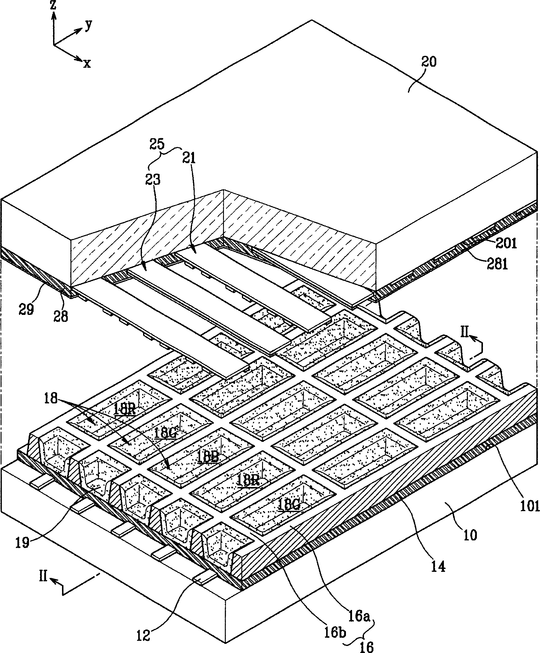
[0028] figure 1 is a partially exploded perspective view of a plasma display panel according to a first embodiment of the present invention,

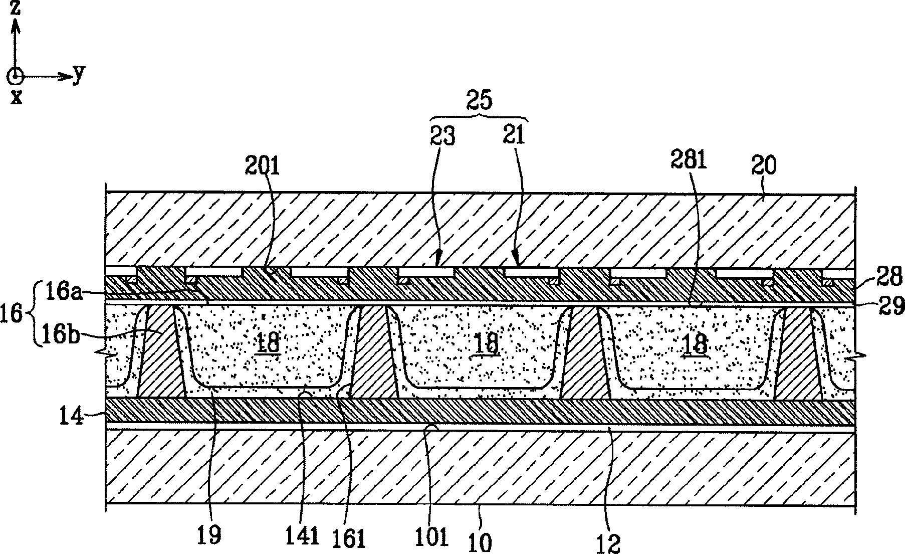
[0029] figure 2 for along figure 1 Partial cross-sectional view of line II-II.

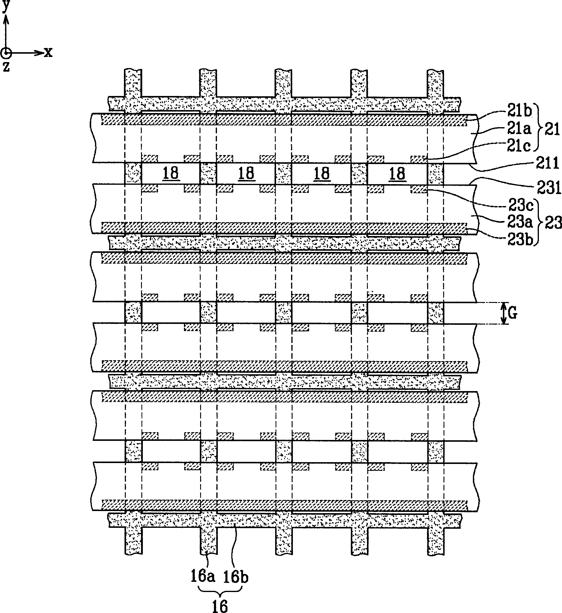
[0030] see figure 1 and 2 , in the plasma display panel (PDP) according to the first embodiment of the present invention, the first substrate 10 (hereinafter referred to as the rear substrate) and the second substrate 20 (hereinafter referred to as the front substrate) are placed opposite to each other and have A gap is predetermined, and the space between the substrates 10 and 20 is divided into at least one ...


PUM


Abstract

The present invention provides a plasma display device having an improved electrode structure capable of improving the contrast of a plasma display panel and reducing a discharge firing voltage. A plasma display panel according to an embodiment of the present invention includes a first substrate and a second substrate placed opposite to each other, barrier ribs arranged in a space between the first substrate and the second substrate to define at least one discharge cell, along Address electrodes formed in a first direction and display electrodes formed in a second direction crossing the first direction. The display electrode includes a bus electrode formed extending in the second direction, extension electrodes extending from the bus electrode toward the center of each discharge cell and facing each other in the discharge cells with a discharge gap interposed therebetween, and extended electrodes disposed in the discharge cells. The front ends of the extended electrodes and the auxiliary electrodes facing each other.

Description

technical field [0001] The present invention relates to a plasma display panel, in particular, to a plasma display panel with an improved electrode structure. Background technique [0002] In general, a plasma display panel (hereinafter referred to as PDP) is a display device in which vacuum ultraviolet (VUV) emitted from plasma generated by gas discharge excites phosphors to emit visible light, thereby forming a predetermined image. [0003] PDPs can be manufactured as large screens with a thickness of less than 10 cm and a diagonal of more than 60 inches. Since it is a self-emissive display device, like a cathode ray tube display, there is no distortion due to viewing angle, and it has outstanding color reproduction. In addition, its manufacturing process is simpler than that of a liquid crystal display device, and thus the PDP has advantages in manufacturability and cost. Accordingly, PDPs have been proposed as next-generation flat panel displays and televisions for ind...

Claims


Application Information

Patent Timeline
IPC IPC(8): H01J11/12H01J11/22H01J11/24H01J11/26H01J11/32H01J11/34H01J11/36H01J11/38H01J11/40H01J11/42H01J11/44H01J11/50
CPCH01J11/12H01J11/24H01J2211/245H01J11/22
Inventor 崔勋永许民崔荣镀朴鋉俱
Owner SAMSUNG SDI CO LTD
Why Eureka
Eureka Blog
Learn More