

Vehicle body CAN bus controlling system
A CAN bus, automobile body technology, applied in the field bus control system field, can solve the problem of no CAN technology, and achieve the effect of simple wiring, convenient function expansion, and improved equipment level
- Summary
- Abstract
- Description
- Claims
- Application Information
AI Technical Summary
Problems solved by technology
Method used
Image

Examples
Embodiment Construction
[0066] The present invention will be described in further detail below in conjunction with the accompanying drawings.
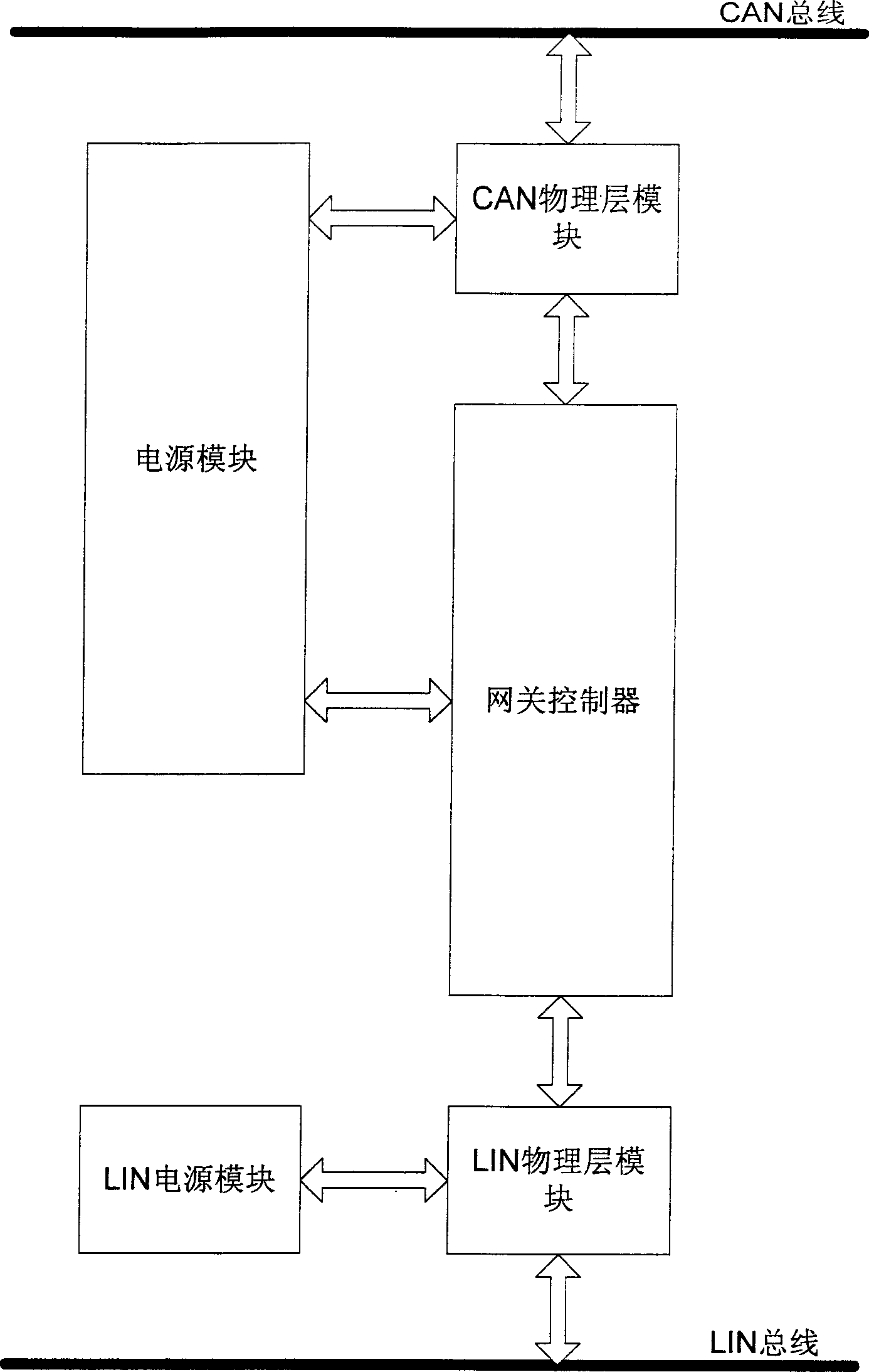
[0067] Such as figure 1 Shown, the present invention comprises CAN-LIN gateway, CAN control module and LIN control module three parts, namely:
[0068] -CAN-LIN gateway, connects two physically independent CAN networks or LIN networks, and realizes data exchange between high-speed and low-speed network systems, runs CAN bus protocol and LIN bus protocol, and completes it through CAN control module or LIN control module Distributed control of automotive electronic components, transmit LIN messages to CAN network, where LIN devices work as slave devices, received LIN messages will be transmitted to CAN network, LIN identifiers are converted into CAN identifiers, LIN The data is transmitted through the CAN object; when the CAN-LIN gateway requests transmission, the CAN identifier is converted into a LIN identifier, the data of the CAN object is stored in the bu...
PUM
 Abstract
Description
Claims
Application Information