Rotor iron core of motor and small motor

A technology of rotor iron core and small motor, applied in the direction of magnetic circuit rotating parts, winding insulation shape/style/structure, magnetic circuit shape/style/structure, etc. It can prevent bending and deformation of the core piece, suppress bending and damage, and increase the joint area.

Inactive Publication Date: 2006-06-07
SANKYO SEIKI MFG CO LTD
View PDF3 Cites 3 Cited by
  • Summary
  • Abstract
  • Description
  • Claims
  • Application Information

AI Technical Summary

Problems solved by technology

However, if riveting is used to obtain sufficient joint strength between the iron core and the rotating shaft, the rotating shaft will be deformed due to the deformation of the core pieces caused by the riveting force.
In addition, there is a problem that the core loss increases due to the deformation of the core piece, which reduces the motor characteristics.
When the number of lamination sheets of the core increases, the riveting force of the core pieces on the inside of both end surfaces is lower than that of the two end surfaces of the core, and there is a problem that the core pieces run idle or shift.

Method used


Image

  • Rotor iron core of motor and small motor
  • Rotor iron core of motor and small motor
  • Rotor iron core of motor and small motor

Examples


Embodiment 1

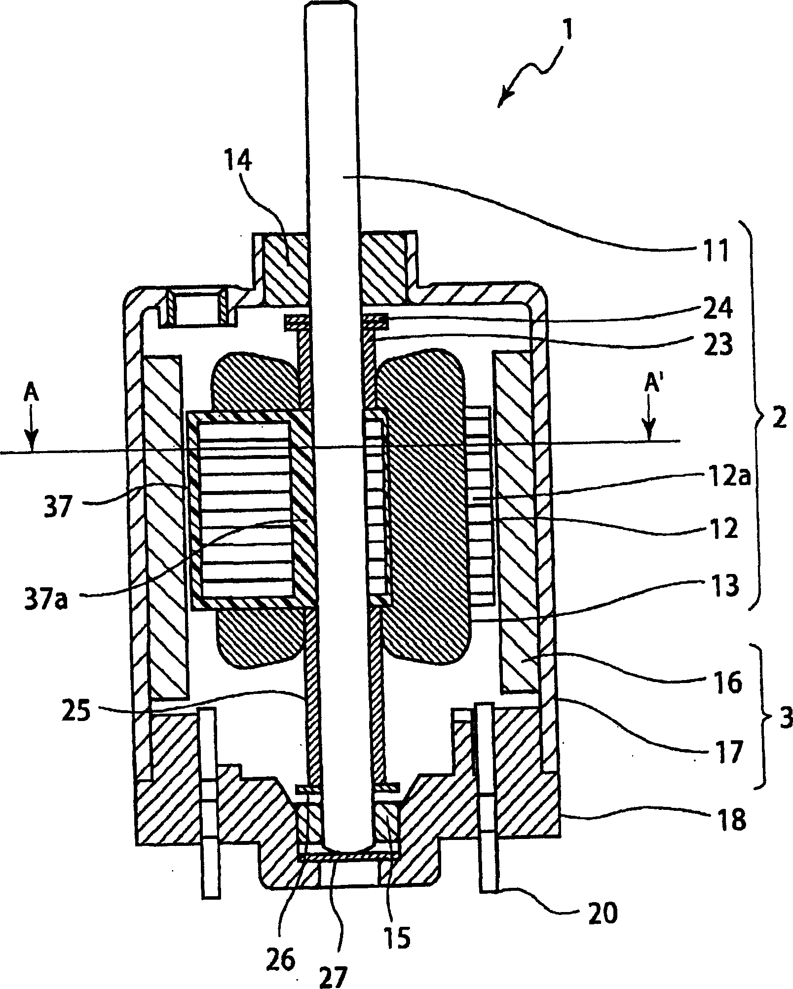
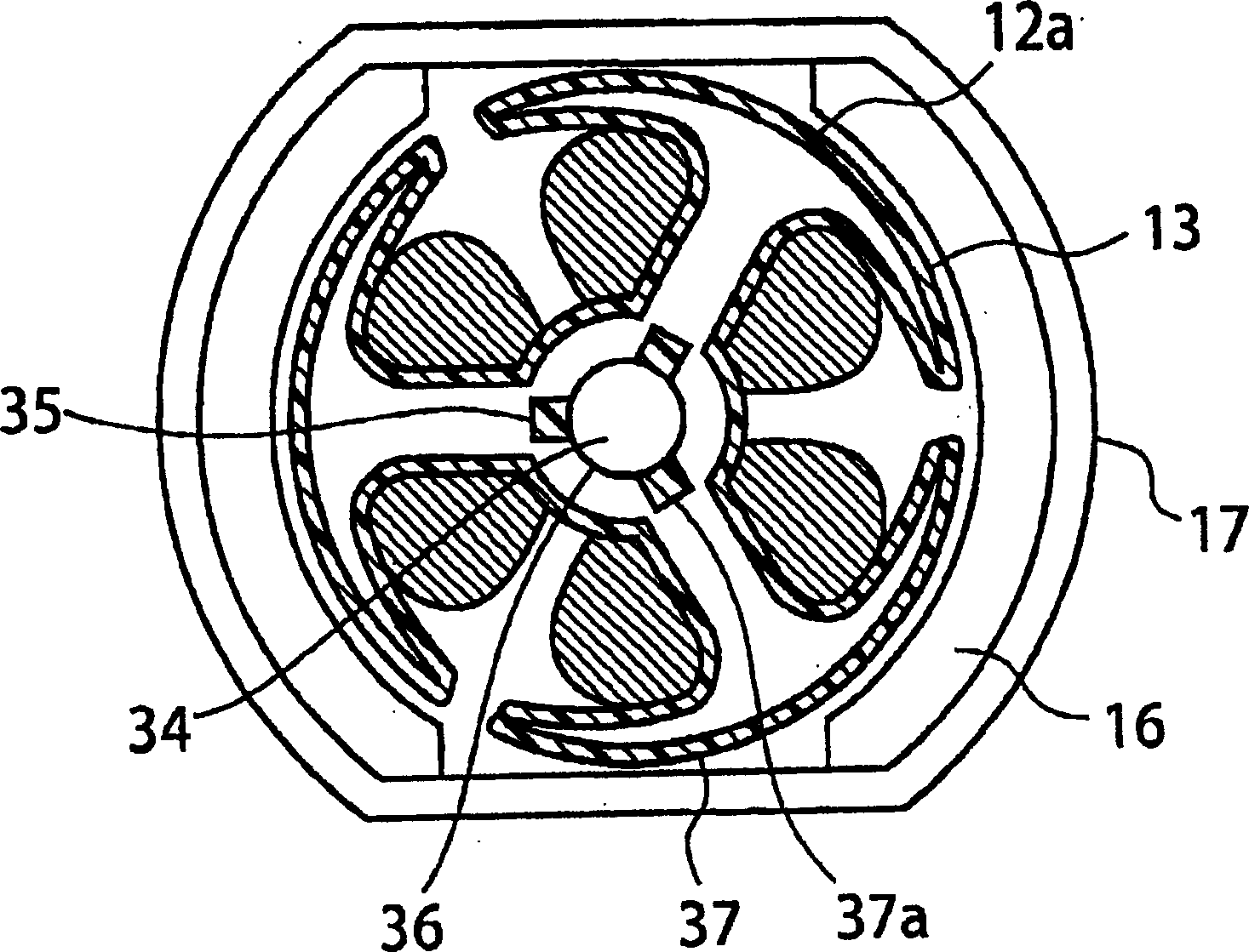
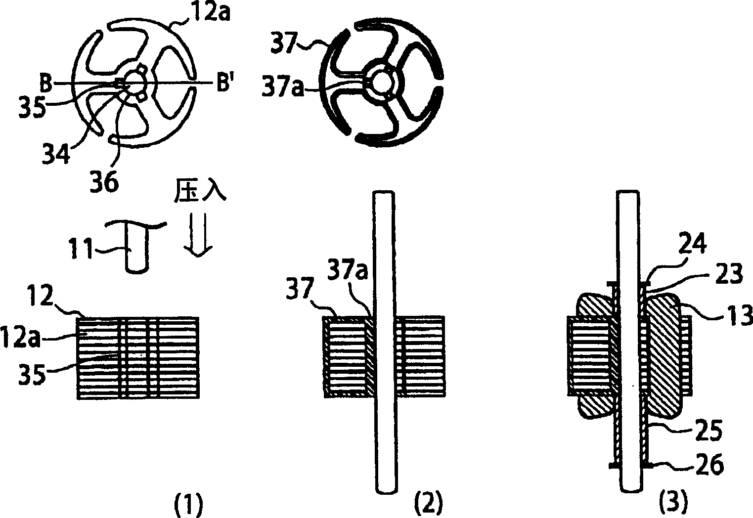
[0033] figure 1 It is a sectional view of main parts of the motor according to Embodiment 1 of the present invention. figure 2 It is seen from the vertical direction relative to the rotation axis of the motor of Example 1 figure 1 A cross-sectional view of part A-A' of . image 3 It is a diagram showing a process of forming the rotor part by pressing the cores stacked on the rotating shaft, forming a resin film on the gap between the core pieces, and winding a winding on the rotor core after joining the rotating shaft and the core. . In addition, the term "rotor core" refers to a member in which a rotating shaft is press-fitted into the core and joined with a resin film in the gap, and the term "rotor coil" refers to a member in which a winding is wound on the rotor core.

[0034] figure 1In the motor 1, a winding 13 is wound on a core 12 formed by laminated core pieces 12a, and a rotor core in which a rotating shaft 11 made of stainless steel is press-fitted, and a beari...


PUM


Abstract

The present invention provides a rotor core in which the rotating shaft of a motor used in information equipment and the like is not bent or damaged when the rotating shaft core is pressed into the core. The through hole (34) of the iron core sheet (12a) is provided with a press-fit part (36) and a gap part (35), and the rotating shaft (11) is pressed into the iron core (12) formed by laminating the iron core sheet (12a). A resin film (37a) joining the rotating shaft (11) and the core (12) is formed on the gap portion (35), thereby forming a rotor core that suppresses bending and damage of the rotating shaft (11), and provides a small, low-noise, Motor with high reliability.

Description

(1) Technical field [0001] The present invention relates to a small motor used in the field of information equipment for lens driving of cameras and recording and reproducing devices such as CD and DVD, and particularly relates to the rotor core thereof. (2) Background technology [0002] In recent years, there has been an increasing demand for miniaturization of motors used in information equipment such as mobile personal computers. For example, in a rotor core in which the rotating shaft of a motor used in information equipment is pressed into the core, there are sliding noises of bearings caused by bending and damage of the rotating shaft as the size is reduced; noise caused by shaft misalignment ; And the problem of reduced reliability of the motor due to bending and damage of the rotating shaft. [0003] Conventionally, in a large number of inner rotor motors used in information equipment as described above, the rotating shaft is press-fitted and fixed into a through-h...

Claims


Application Information

Patent Timeline
Patent Type & Authority Applications(China)
IPC IPC(8): H02K1/28H02K3/34
CPCH02K1/28
Inventor 赤羽诚
Owner SANKYO SEIKI MFG CO LTD
Why Eureka
Try Eureka