Electrification railway contact net measuring aiming method based on camera

A technology for electrified railways and cameras, which is applied to railway vehicle shape measuring instruments, radio wave measuring systems, measuring devices, etc., can solve problems such as difficulty in precise and rapid aiming, and achieve high aiming accuracy, improve aiming accuracy, and eliminate parallax effects.

Active Publication Date: 2006-06-14
济南蓝动激光技术有限公司
View PDF0 Cites 11 Cited by
  • Summary
  • Abstract
  • Description
  • Claims
  • Application Information

AI Technical Summary

Problems solved by technology

This creates great difficultie

Method used


Image

  • Electrification railway contact net measuring aiming method based on camera
  • Electrification railway contact net measuring aiming method based on camera

Examples


Embodiment

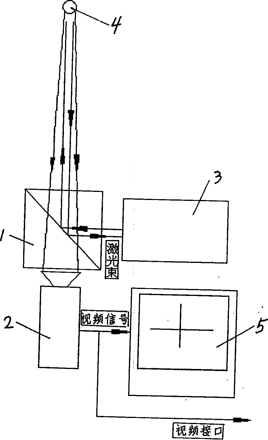
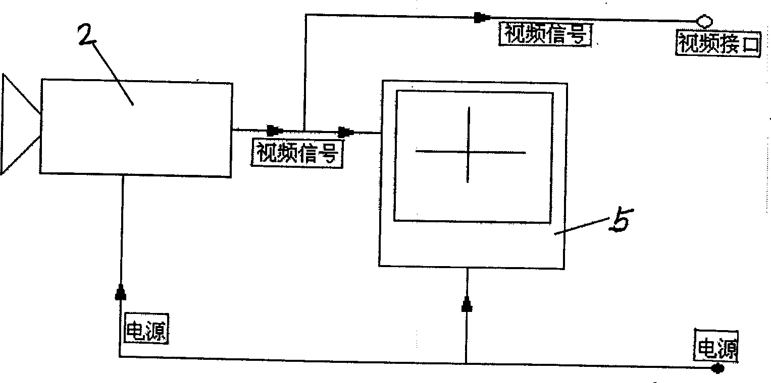
[0013] figure 1 The structural principle diagram of the present invention is given. The aiming method is to place a beam splitting prism 1 on the left side of the laser distance sensor 3 used for measuring catenary line guide height, and make the outgoing light beam of the laser distance sensor 3 perpendicular to the right incident surface of the beam splitting prism 1 . A camera 2 is placed directly below the lower incident surface of the beam splitting prism 1 , and the optical axis of the camera 2 is perpendicular to the lower incident surface of the beam splitting prism and perpendicular to the outgoing beam of the laser distance sensor 3 . The video output of camera 2 is connected with TFT display 5 .

[0014] The image of the electrified railway catenary line directly passes through the beam splitting prism 1 and reaches the camera 2, and the outgoing beam of the laser distance sensor 3 reaches the catenary line through a 90-degree turn. The optical path of the camera ...


PUM


Abstract

The invented aiming method is characterized by that a beam splitter prism is placed in the front of laser distance sensor for measuring contact network line guide height to make the exit light-beam of the laser distance sensor be perpendicular to the incident face of beam splitter prism. A camera head is placed under the incident face of the beam splitter prism to make the optical axis of said camera head be perpendicular to incident face of the beam splitter prison, and perpendicular to exit light-beam of laser distance sensor, the video output of the camera head is connected with display. When the image of measured object is coincided with crosspoint of cross-line of camera head, the aiming can be define.

Description

technical field [0001] The invention relates to a catenary measuring and aiming method for detecting geometric parameters of an electrified railway catenary. Background technique [0002] The currently known aiming method of electrified railway catenary adopts an optical method, which is composed of a group of lenses and a cross differentiation plate. Coincidence means aiming at the target. [0003] The image seen on the observation screen by optical aiming method has a fixed field of view, and the size of the image seen cannot be adjusted and is an inverted image, which makes it impossible for workers to quickly identify the network cable to be tested. At the same time, it is greatly affected by ambient light, and strong or weak sunlight will cause blurred images. The aiming optical axis and the distance measuring optical axis are not coaxial. This creates great difficulties for precise and rapid aiming. Contents of the invention [0004] Aiming at the deficiencies of...

Claims


Application Information

Patent Timeline
IPC IPC(8): B61K9/08G01C3/00G01S17/08G01S17/46
Inventor 王道睿陈强李朝政林宪旗张文亮李文甫
Owner 济南蓝动激光技术有限公司
Why Eureka
Try Eureka