Non negative pressure steady flow automatic water supply equipment

An automatic water supply, no negative pressure technology, applied in water supply devices, water saving, configuration of water supply pools, etc., can solve problems such as water pollution and energy waste

Inactive Publication Date: 2006-06-14
SHANGHAI LIANCHENG(GRP) CO LTD
View PDF0 Cites 9 Cited by
  • Summary
  • Abstract
  • Description
  • Claims
  • Application Information

AI Technical Summary

Problems solved by technology

[0003] The purpose of the present invention is to solve the problems existing in the traditional water supply and frequency conversion constant pressure water supply device in the prior art, and to provide a non-negative pressure device that can completely solve the

Method used


Image

  • Non negative pressure steady flow automatic water supply equipment

Examples


Embodiment Construction

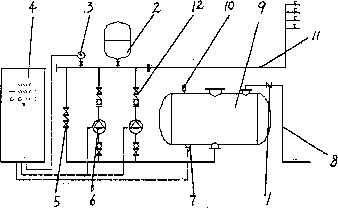
[0005] The figure includes a water inlet check valve 1, a pressure stabilizing tank 2, a pressure sensor 3, a frequency conversion cabinet 4, a control valve 5, a feed water pump 6, and a liquid level sensor 7. Tank 9, a vacuum eliminator 10 is connected to the steady flow tank 9, the outlet of the steady flow tank 9 is connected with two feed pumps 6 and a control valve 5, and an outlet pipe 11 is connected with three check valves 12, the check valves 12 are respectively connected to the outlet of the feed pump 6 and the outlet of the control valve 5, the outlet pipe 11 is connected with the surge tank 2 and the pressure sensor 3, the liquid level sensor 7, the pressure sensor 3, and the feed water pump 6 is connected to the frequency conversion cabinet 4. During use, the water of the tap water pipe network enters the steady flow tank 9 by the tap water inlet pipe 8, and the air in the tank 9 is discharged from the vacuum eliminator 10, and the vacuum eliminator 10 closes auto...


PUM


Abstract

The invention relates to no negative pressure steady flow auto water-supply installation. It includes influent back valve, steady head tank, pressure sensor, frequency conversion tank, control valve, feed pump, and liquid level sensor. Its feature is has a steady flow tank connected to tap water influent pipe; the steady flow tank is connected with vacuum breaker; its outlet is connected with at least two pump and control valve. One discharging tube is connected with three back valves; the back valve is respectively connected to pump outlet and control valve outlet; the discharging tube is connected with steady head tank and pressure sensor; the liquid level sensor, pressure sensor, and pump are connected with frequency conversion tank. The advantages of the invention are that it can prevent water pollution caused by secondary water-supply installation; and it also can reduce electric energy consumption.

Description

technical field [0001] The invention relates to an automatic water supply device, in particular to an automatic water supply device with no negative pressure and steady flow. Background technique [0002] At present, when the general water supply equipment is directly connected to the water pipe network, there will be negative effects, because the flow rate of the water pump is often greater than the water flow of the water pipe, which will cause a drop in the pressure of the pipe network and affect the water use of surrounding users. In order to solve the irrationality of this water supply scheme, the traditional water supply method needs to build a water source water tank and a roof water tank at the inlet of the water pump. There are three problems in this traditional water supply scheme. First, the water source water tank of the water pump and the roof water tank are both It is easy to have pollution problems, because there are overflow outlets in the design of the pools...

Claims


Application Information

Patent Timeline
IPC IPC(8): E03B11/16
CPCY02A20/00
Inventor 周绪安龚寿奇
Owner SHANGHAI LIANCHENG(GRP) CO LTD
Why Eureka
Try Eureka