Composite stainless steel rod with rainforced structure and its mfg. method

A technology of stainless steel strips and reinforcing structures, applied in the direction of slender elements, building elements, etc., can solve problems such as unsatisfactory effects

Inactive Publication Date: 2006-06-14
李峰
View PDF1 Cites 3 Cited by
  • Summary
  • Abstract
  • Description
  • Claims
  • Application Information

AI Technical Summary

Problems solved by technology

During the implementation of the utility model patent ZL200420064102.1, the steel wire

Method used


Image

  • Composite stainless steel rod with rainforced structure and its mfg. method
  • Composite stainless steel rod with rainforced structure and its mfg. method
  • Composite stainless steel rod with rainforced structure and its mfg. method

Examples


specific Embodiment 1

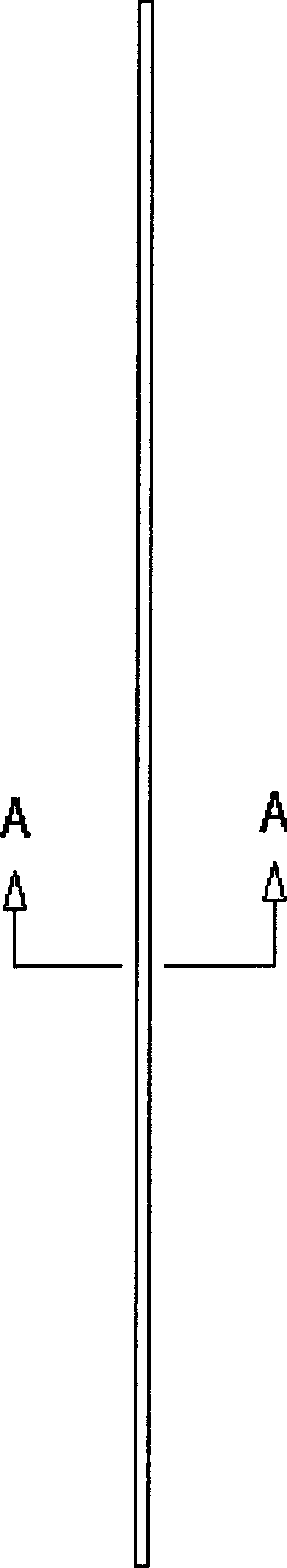
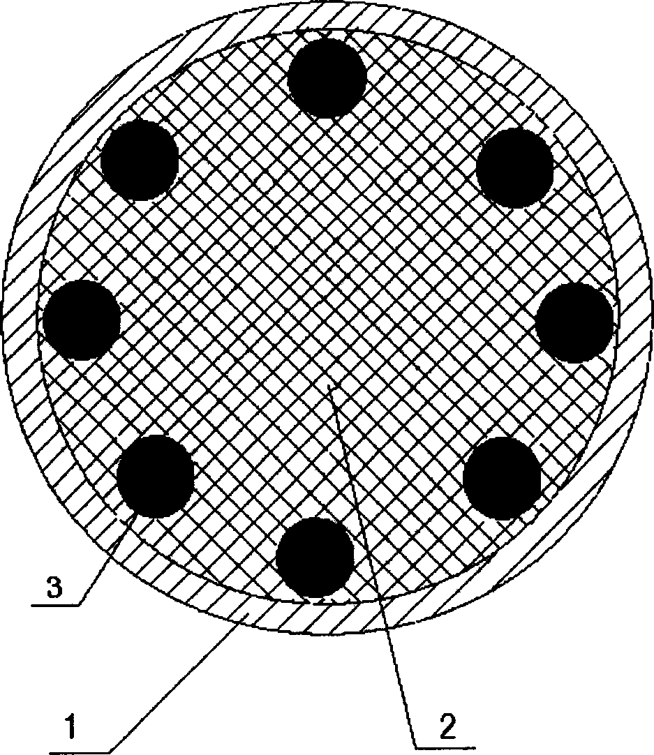
[0065] Specific embodiment 1, such as figure 1 , figure 2 shown along the figure 1 Schematic diagram of planing at A-A of the middle composite stainless steel bar, such as figure 2 As shown, the stainless steel pipe 1 is filled with artificial stone 2, the steel wire 3 is evenly placed along the inner wall of the stainless steel pipe 1, and the average distance between the steel wire 3 and the inner wall of the stainless steel pipe 1 is less than 3 mm.

specific Embodiment 2

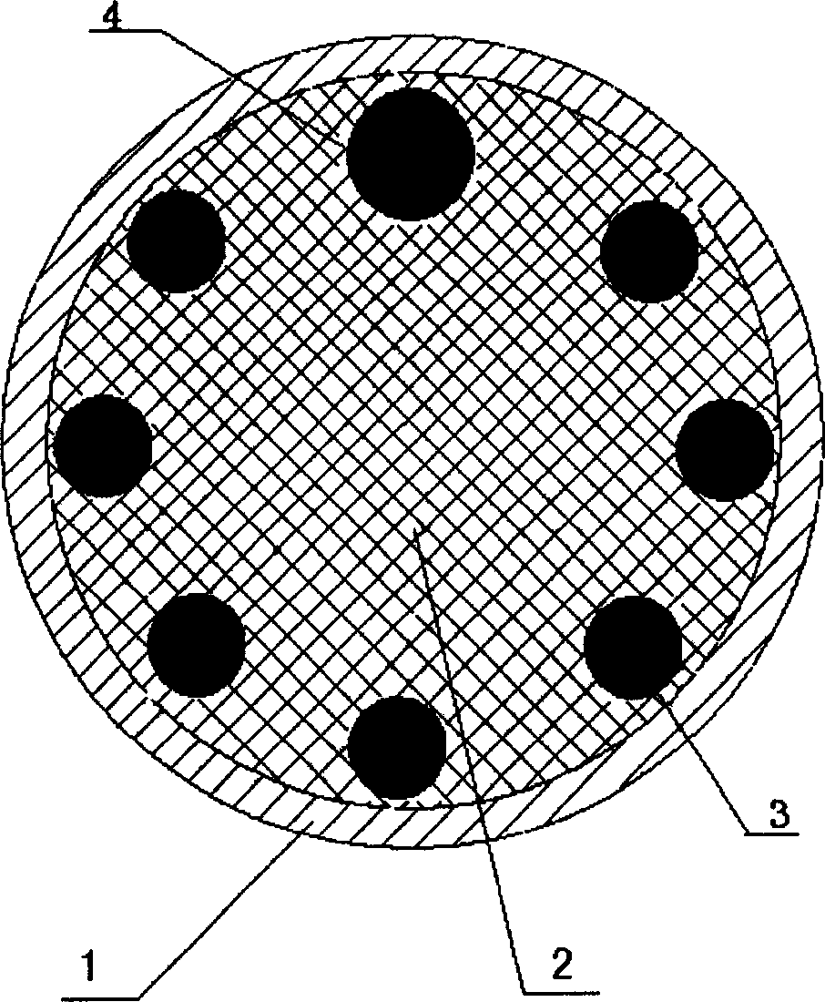
[0066] Specific embodiment 2, such as image 3 as shown, image 3 Among them, in the stainless steel pipe 1, there is a high-hardness steel wire 4 in addition to the steel wire 3. The high-hardness steel wire 4 is closely combined with the artificial stone, which can play a good anti-saw function and is not easy to be broken.

specific Embodiment 3

[0067] Specific embodiment 3, such as Figure 4 as shown, Figure 4 Among them, the filling is all high-hardness steel wire 4, and the outer surface of the high-hardness steel wire 4 is a rough surface, which is closely combined with the artificial stone.


PUM

PropertyMeasurementUnit
Thicknessaaaaaaaaaa
Lengthaaaaaaaaaa
Lengthaaaaaaaaaa

Abstract

The invention relates to a composite stainless steel bar with a reinforced structure and its manufacture method. The composite stainless steel bar with the packing is reinforced by increasing wire near the inwall of the composite stainless steel bar. This kind of the composite stainless steel bar has high strength so it can resist beating and bending.

Description

【Technical field】 [0001] The invention relates to a composite stainless steel bar with a reinforced structure and a manufacturing method thereof, in particular to a composite stainless steel bar with fillers and a manufacturing method thereof, belonging to the field of decorative material manufacturing. 【Background technique】 [0002] At present, known slender stainless steel bars are generally made of stainless steel pipes (seamed pipes or seamless pipes, whose cross-sections have circular, elliptical, rectangular or polygonal and various special-shaped pipes), and are made of stainless steel. Stainless steel pipes have a beautiful surface after polishing, and are often used in places that require decoration, such as making anti-theft nets for households. Due to the high price of stainless steel, when people produce stainless steel pipes for decoration, the pipe wall will be thinner to reduce costs, but the strength of stainless steel pipes will be reduced at the same time,...

Claims


Application Information

Patent Timeline
IPC IPC(8): F16S3/00
Inventor 李峰
Owner 李峰
Why Eureka
Try Eureka