Electronci alarming guard for separating dangerous area

A dangerous area, electronic technology, applied in the direction of alarms, burglar alarms, fences, etc., can solve the problems of not being able to play a warning role and personal safety threats, and achieve the effect of beautiful appearance, firm structure, and tight integration

Inactive Publication Date: 2006-06-14
KGE
View PDF0 Cites 13 Cited by
  • Summary
  • Abstract
  • Description
  • Claims
  • Application Information

AI Technical Summary

Problems solved by technology

The working voltage of the substation is generally above 11KV, which poses a great threat to personal safety. However, the existing common barriers usually hang protective nets on several fence poles, which cannot play an effective warning role, especially in During construction late at night, workers are mentally exhausted and will break out of the safe area if they are not paying attention, causing serious consequences

Method used


Image

  • Electronci alarming guard for separating dangerous area
  • Electronci alarming guard for separating dangerous area
  • Electronci alarming guard for separating dangerous area

Examples


Embodiment 1

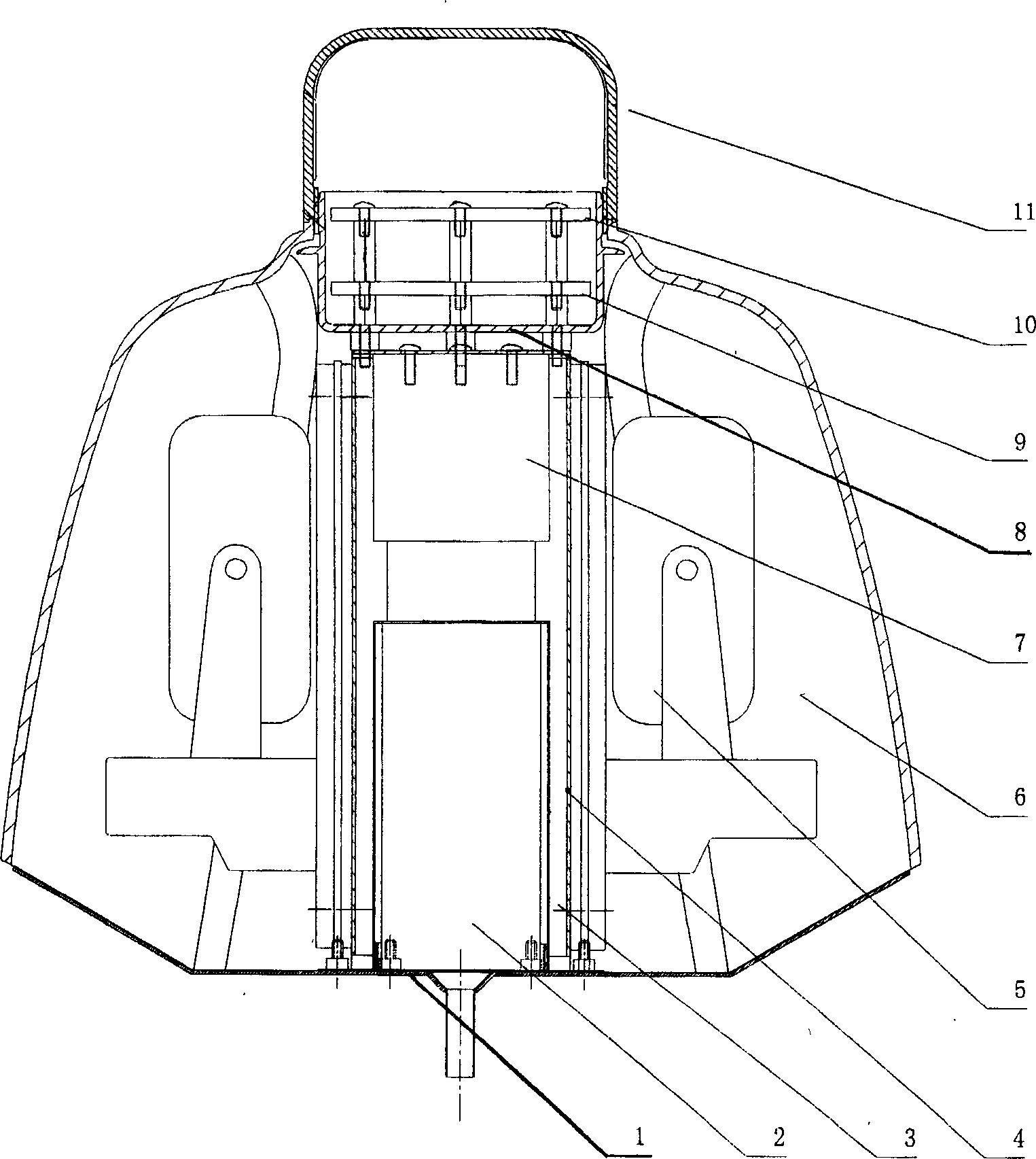
[0032] The present invention comprises 4 railing poles, and the infrared ray contrasting device is housed respectively on the railing poles, and the infrared ray projector emits 2 bunches of infrared rays, and the interval between them is 8cm, and safety net is hung between the fence poles, enclosing a quadrilateral, as Figure 7 As shown, one side is an exit, and there is no infrared beam in between; the other three sides are provided with infrared beams, when the beam is blocked, the electronic alarm device will send out an audible and visual alarm signal. therefore, Figure 7 There are 2 infrared light emitters in the directing device A, two infrared light receivers in the directing device B, one infrared light emitter in the directing device C, and one infrared light receiver in the directing device D. Infrared radiation device such as figure 1 As shown, it is composed of shell 6, bottom plate 1, battery clip 3, metal connector 8 and lampshade 11, etc., lampshade 11 is lo...

Embodiment 2

[0043] The invention includes two fence poles, on which infrared beams are respectively installed, and the infrared light projector emits three beams of infrared rays, the interval between them is 4cm, when the infrared beams in between are blocked, the electronic alarm device will send out sound and light alarm Signal.

[0044] The structure, installation, and wiring of the infrared radiation device are as in Example 1. The difference is that there is only one infrared projector inside the infrared radiation device on one of the fence poles, and only one infrared projector is provided inside the other radiation device. Infrared receiver.

Embodiment 3

[0046] The present invention comprises 3 railing poles, on which the infrared ray directing device is installed respectively, and the infrared ray projector emits 4 bundles of infrared rays, the interval between them is 3cm, safety nets are hung between the railing poles, forming a triangle, one side of which is There is no infrared beam between the exits; there is an infrared beam between the other two sides. When the beam is blocked, the electronic alarm device will send out an audible and visual alarm signal. Therefore, two infrared light emitters are installed in the directing device on the fence pole opposite to the exit side, and one infrared light receiver is respectively installed in the directing device on the other two fence poles.

[0047] The structure, installation and wiring of the infrared radiation device are as in Example 1.


PUM


Abstract

The invention relates to an electronic alarming guard bar for isolating the electrified regions such as power plants, power stations and other places, the construction fields and other dangerous regions, comprising two or above bars provided with a photoelectric beam detector, which comprises a photoelectric beam transmitter and a photoelectric beam receiver, in pairs arranged on different bars and connected with an alarm device each. It is convenient to install and simple to operate and able to reduce fatal accidents.

Description

technical field [0001] The invention relates to an electronic alarm guardrail for isolating electrified areas, construction sites and other dangerous areas of power plants and power stations. Background technique [0002] At present, in the power system, especially in the substation, in order to ensure normal power supply, it must be operated with electricity during construction. The working voltage of the substation is generally above 11KV, which poses a great threat to personal safety. However, the existing common barriers usually hang protective nets on several fence poles, which cannot play an effective warning role, especially in During construction late at night, workers are mentally exhausted and will break out of the safe area if they are not paying attention, causing serious consequences. [0003] "Safety first, prevention first", personal safety is the top priority. Compared with ordinary barriers, electronic fences can increase the safety awareness of on-site con...

Claims


Application Information

Patent Timeline
Patent Type & Authority Applications(China)
IPC IPC(8): G08B13/183E04H17/00
Inventor 金基民代保明郭克罗兵张彤蔡清伟梁昌宇王经辉
Owner KGE
Why Eureka
Try Eureka