Device for positioning and removing thread bobbins in a textile machine

A technology for textile machinery and spools, applied in the field of textile machinery, can solve the problems of difficult adjustment, loosening of the thread in the direction of rotation of the spool, and difficulty in adjustment.

Inactive Publication Date: 2006-06-21
RIETER TEXTILE MACHINERY FRANCE
View PDF2 Cites 4 Cited by
  • Summary
  • Abstract
  • Description
  • Claims
  • Application Information

AI Technical Summary

Problems solved by technology

[0015] A first disadvantage is that, especially if the removal means is a ramp along which the spool rolls down, at the time of removal, when the spool rolls down the ramp, the The direction of rotation of the spool described above will loosen the thread
[0016] A second disadvantage is that the tube dispensing hopper and the fork forming the clamping and positioning device are two moving parts, so that when transferring an empty tube, the two parts must be precisely aligned, and the The required adjustment is difficult to achieve
[0017] A third disadvantage is that, given the state of the art, as the diameter of the bobbin changes, the positioning of the forks causes a change in force that must be compensated for using a monitoring device that is difficult to adjust
[0018] Finally, a fourth disadvantage is that the spool tends to move sideways when placed on a ramp or other form of removal
In fact, the spool has a tendency to slide asymmetrically, given that it usually has a straight edge and a rounded edge, and this makes the spool more inclined to slide relative to the straight edge, resulting in an offset effect

Method used


Image

  • Device for positioning and removing thread bobbins in a textile machine
  • Device for positioning and removing thread bobbins in a textile machine
  • Device for positioning and removing thread bobbins in a textile machine

Examples


Embodiment Construction

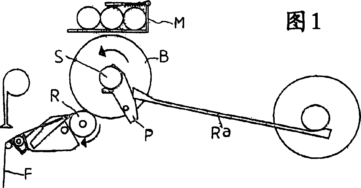
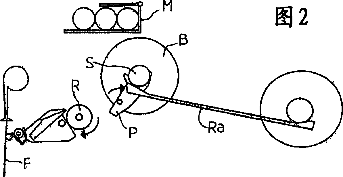
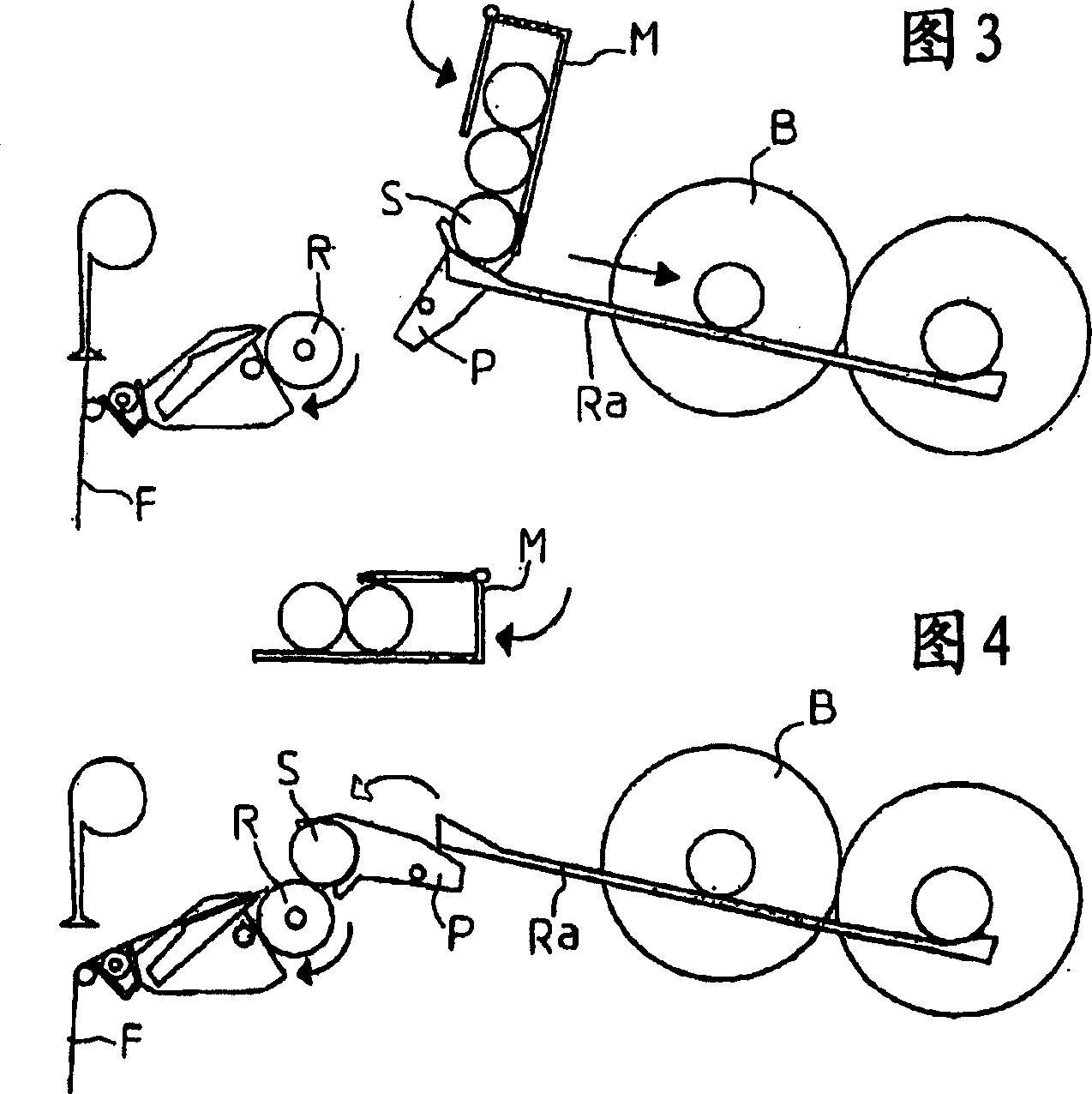
[0038] Figure 5 The textile machine shown in is of the type known to comprise at least one receiving cylinder 1 for thread 2 controlled by a reciprocating system 3 for forming bobbins B on a tubular support 4 . As will be explained in the rest of the description, during the actual winding operation, said tubular support 4 is rotatably mounted in a clamping and positioning articulation, which notably comprises a swing arm 5 which 5 Form a fork.

[0039] The empty tubular support 4 is mounted in a device 6 which acts as a distributor.

[0040] The bobbin B is removed via at least one ramp 7 sloping substantially downwards from the winding area. It must be noted that the spool can be removed by other means.

[0041]According to one aspect of the invention, said motor-driven receiving cylinder 1 is arranged in front of said tubular support 4 in said winding position. As a result, the formation of the bobbin B occurs after the cylinder 1 with respect to the wire arrival. The w...


PUM


Abstract

The invention relates to a device, characterized in that both the output cylinder (1) and the tubular support (4) are arranged in a winding position in a defined direction of rotation, such that the wire passes through the bottom of said output cylinder to the point of contact, and is wound onto the top of the tubular support, and the formation of the bobbin and the separation movement towards the removal device (7) are carried out in a direction opposite to the direction of arrival of the wire, and for dispensing The means (6) of said tubular support remains fixed.

Description

technical field [0001] The invention relates to the technical field of textile machinery, in particular doffing operations. [0002] In particular, the invention may be applied in the fields of textile machines, cabling, twisting and texturing machines and, more generally, in the texturing of threads. technical background [0003] The problem in textile machines of this type consists in particular of being able to remove and dismantle the tubular support on which the bobbin is formed, to replace it with an empty tubular support and to restart the production of a new bobbin . [0004] These operations are generally referred to as "doffing" by those skilled in the art. They include interrupting the process of winding on a bobbin that has reached the required weight or yardage, braking and then removing the full bobbin, replacing it with an empty tube and then restarting the winding process. This sequence is usually done manually, but is now done step by step automatically o...

Claims


Application Information

Patent Timeline
Patent Type & Authority Applications(China)
IPC IPC(8): B65H67/04
CPCB65H67/0405B65H2701/31
Inventor G·内勒X·艾罗P·弗莱雄
Owner RIETER TEXTILE MACHINERY FRANCE
Why Eureka
Try Eureka